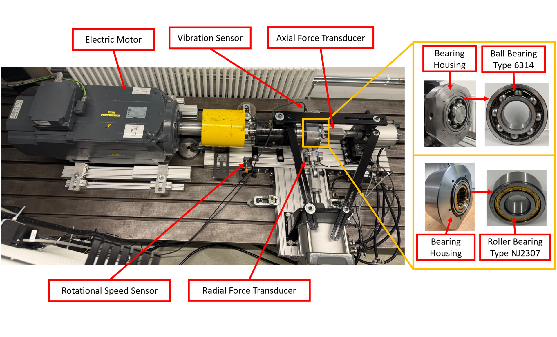
The measurements were performed on an APS 58 bearing test rig, which consists of an electric drive unit, a bearing housing, and two pneumatic actuators for applying radial and axial loads. The applied forces were measured using HBM U2B tension/compression force transducers, with radial and axial measurement ranges of ±20 kN and ±10 kN, respectively. The force signals were processed and recorded using MATLAB/Simulink.
The rotational speed was measured with an Autosen A0014 optical sensor at a sampling frequency of 1 kHz. Vibration data were acquired using a PCB 603C01 ICP piezoelectric accelerometer mounted on the bearing housing and a National Instruments (NI) data acquisition system.
For the 6314 deep-groove ball bearings, vibration signals were recorded at sampling frequencies of 51.2 kHz, 25.6 kHz, and 12.8 kHz over a duration of 120 s per measurement. For the NJ2307 cylindrical roller bearing, vibration signals were recorded at 10 kHz over a duration of 60 s per measurement.
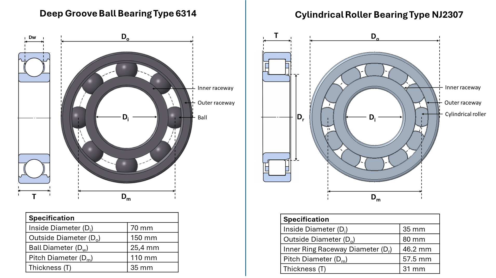
Both bearing types were tested on the same test rig and under the same load points. Their corresponding bearing housings were used for deep-groove ball bearings and cylindrical roller bearings during testing respectively.