
Properties of Wear-Resistant MoN Films on Microengineered Substrates


1
Research Institute of Innovative Surfaces FINO, Aalen University, Beethovenstr. 1, D-73430 Aalen, Germany
2
Department of Plasma Surface Technology and Materials Physics, Research Institute for Precious Metals and Metal Chemistry, D-73525 Schwäbisch Gmünd, Germany
*
Author to whom correspondence should be addressed.
Coatings 2022, 12(9), 1232; https://doi.org/10.3390/coatings12091232
Submission received: 22 July 2022
/
Revised: 11 August 2022
/
Accepted: 17 August 2022
/
Published: 24 August 2022
(This article belongs to the Special Issue Recent Developments of Micro and Nano Tribological Coatings)
Abstract
:Molybdenum nitride layers were deposited onto the substrates of high-speed steel using high-power impulse magnetron sputtering. To control the tribological properties of these wear-resistant surfaces, a sophisticated pretreatment of the substrates was performed. Both the topography and the composition of the surfaces were modified on a length scale of a few micrometers before the deposition of MoN. For that purpose, a microembossing technique was applied that used specifically prepared diamond stamps. Compositional variations are realized by an additional deposition of silver. Modifying the properties of the wear-resistant surface via this substrate engineering method allowed a significant reduction in the coefficient of friction, a change of the dominant wear process and a possible lifetime increase. Changing the surface topography led to a reduction of friction and, therefore, to reduced mechanical work supplied to the surface. Occurring wear was reduced accordingly. The introduction of silver further reduced the mechanical energy that was available for the abrasion process and led to an additional increase in the lifetime of the surface. It was concluded that not only the wear volume, but also the relevant wear mechanisms could be influenced via a substrate modification.
1. Introduction
Wear-resistant coatings of transition metal nitrides or carbides are ubiquitous in all types of mechanical systems containing surfaces that are in contact under relative motion. In particular, molybdenum nitride has become interesting because of its high performance under extreme conditions (severe deformation under a large load, dry sliding and high temperatures) and its outstanding hardness [1,2,3]. In addition, it has been found that the introduction of surface structures on a micron scale can be a valuable tool to decrease both friction and wear under dry sliding conditions [4,5,6,7,8,9]. Very low coefficients of friction (COFs) are found when combining adequate microstructures with liquid [10] or solid lubricants [11,12,13,14]. From carbide coatings, it has been revealed that laser sintering can also lead to wear-resistant surfaces exhibiting extreme lifetimes [15]. Due to the significant wear resistance of nitride and carbide surfaces, it has been established that it is highly desirable to avoid direct patterning of the material. A sophisticated possibility has been given by the application of so-called “smart substrates”. Using substrates that are thoroughly structured before the deposition of wear-resistant material surfaces, improved properties can be generated [5,6,16].
2. Preparation
In this work we used MoN films that were grown on two series of substrates composed of high-speed steel with a high percentage of chromium and molybdenum (AISI M2; DIN 1.3343). The material was selected for its toughness, high compressive strength and especially its high wear resistance. We used substrates with a modified surface topography that were prepared by a mechanical microembossing process. A second series of substrates was prepared by filling the imprinted voids with a second material; in our case, silver. Silver modified the mechanical properties of the substrate and could, when reacting with the molybdenum nitride film, lead to the formation of lubricant silver molybdates [17]. All of these “smart substrates” were subsequently coated with thin MoN films.
The deposition of MoN was performed using high-power impulse magnetron sputtering (HiPIMS) [18,19,20,21,22,23,24] as it was first published by Kouznetsov et al. [25]. A 3″ sputtering cathode with an Mo-target (purity 99.95 at.%) was operated in a reactive mode. The following process parameters were chosen, as used by Kommer et al. [6]: HiPIMS-pulse pattern: ton = 14 μs, T = 2000 μs, p(N2) = 0.4 Pa and p(Ar + N2) = 0.8 Pa. The peak current density was measured to be i(Peak) = 1.95 A/cm2, resulting in a peak power density of 1.6 kW/cm2 at a target voltage of 840 V. The average target power was 300 W. The substrates were externally biased with U(DC) = −50 V. The coating thickness was about 2 μm as measured by tactile profilometry on a coating step gained by covering a part of the substrate with a razorblade segment. The adhesion of the films was determined to be class HF 2 (very good) by using the Daimler Benz Rockwell C adhesion test (VDI 3198). The indentation hardness was HIT (0.003/10/10/10) = 23 ± 1 GPa (Fischerscope H100 xy p, Helmut Fischer GmbH, Sindelfingen, Germany). This resulted in a film composed of a nanocrystalline γ-Mo2N/δ-MoN phase mixture [6]. The pretreatment of the substrates basically used two particular steps. First, microstructuring was performed using mechanical stamps, similar to the method of Pettersson et al. [26]. The surface of the stamp consisted of microdiamonds with diameters of 10 or 25 µm. These diamonds were partially embedded into a nickel matrix that was deposited onto a body of tungsten carbide (WC). This was achieved by electrochemical dispersion coating. The thickness of the nickel film was typically chosen to be 50% of the size of the respective diamonds. The other half of the diamonds was elevated from the nickel surface and could be used for mechanical embossing. As the tungsten carbide surface at the back of the diamonds exhibited significant hardness, we observed a penetration of the diamonds into the steel substrate.
The preparation of the silver islands was undertaken in three steps. First, a thin titanium layer was deposited by DC sputtering onto the embossed surface to guarantee sufficient adhesion. Subsequently, a 5 µm-thick silver layer was deposited on top. Finally, the silver layer was removed by mechanical polishing whereas the silver inside the voids remained. It was not possible to prepare the MoN films with reasonable properties on a closed silver layer. In this case, insufficient adhesion would lead to non-beneficial results.
3. Results
All coated surfaces were mechanically analyzed using oscillation tribometry under dry conditions. During the measurements, the coefficient of friction was determined. The resulting wear tracks were imaged by white-light interferometry. The volume and surface of the wear tracks were analyzed, finally allowing the identification of the individual wear mechanisms. All displayed results were examples from the measurement series that were collected from various MoN films from about 80 individual experiments. The majority of them performed with films on engineered substrates.
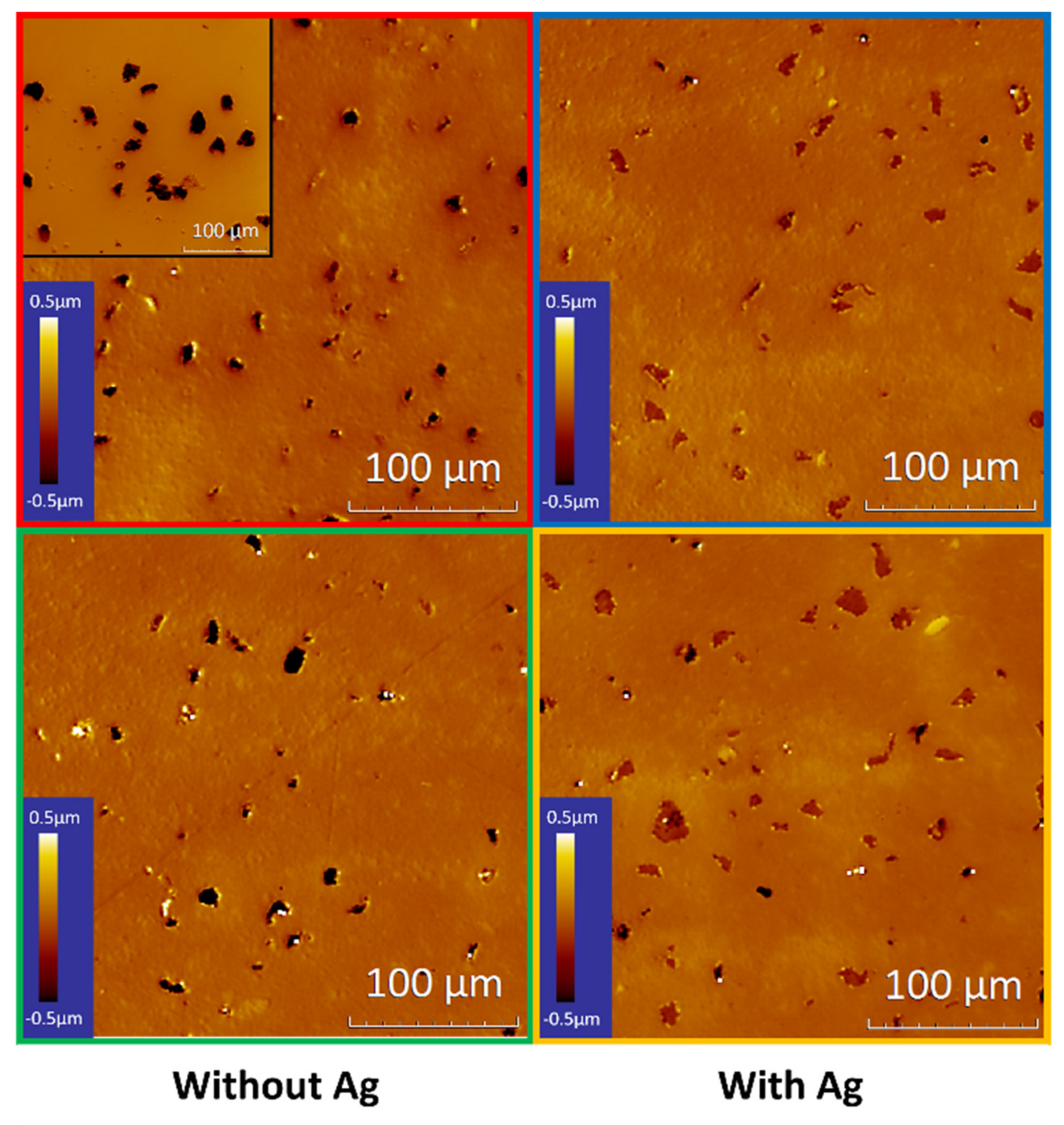
Figure 1 depicts the surface of four characteristic substrates that were used in this work.
The panels in the left column of Figure 1 show the MoN films on embossed surfaces using 10 µm diamonds (top left, red) and 25 µm diamonds (top right, blue). The right column depicts the MoN films on equivalently embossed surfaces where the imprints were filled with silver (bottom left, green and bottom right, yellow). All images show the surfaces after a subsequent deposition of a 2.2 µm-thick MoN layer. A comparison with the corresponding surface before the MoN deposition (inset, top left) shows that the used HiPIMS process basically conserved the topography of the substrate.
For comparison, a MoN film was deposited onto a polished substrate. The substrate and film exhibited a roughness in the order of Ra = 0.013 µm. The surfaces that were prepared by the microembossing process exhibited stochastically distributed imprints with average diameters of 9.7 µm and a depth in the range of 1.3 µm in the case of the 10 µm diamonds and average diameters of 16.4 µm and a depth in the range of 5.0 µm in the case of the 25 µm diamonds, respectively. The surface of the silver-filled imprints was nearly smooth; however, remains of the imprinted structures could be detected. In particular, this was found in the 25 µm structures where the final polishing step removed an amount of silver from the imprints. The typical depth of the remaining structures was up to 0.2 µm.
The tribological properties of these surfaces were analyzed by oscillation tribometry using an Optimol®SRV3 (Optimol Prüfsysteme GmbH, Munich, Germany).
We used a 100Cr6 counterbody (62 HRC) under dry conditions. This set-up was chosen because of its relevance for such applications and to warrant a comparability with previous results [5,6]. The counterbody had a spherical shape with a diameter of d = 10 mm and the used normal force was FN = 50 N.
We chose this extraordinarily large load to realize severe damage to the highly wear-resistant MoN surface. Furthermore, an oscillation frequency of 2 Hz was used with an amplitude of 0.5 mm, leading to a maximal relative velocity in the experiment of vmax = 6.3 mm/s.
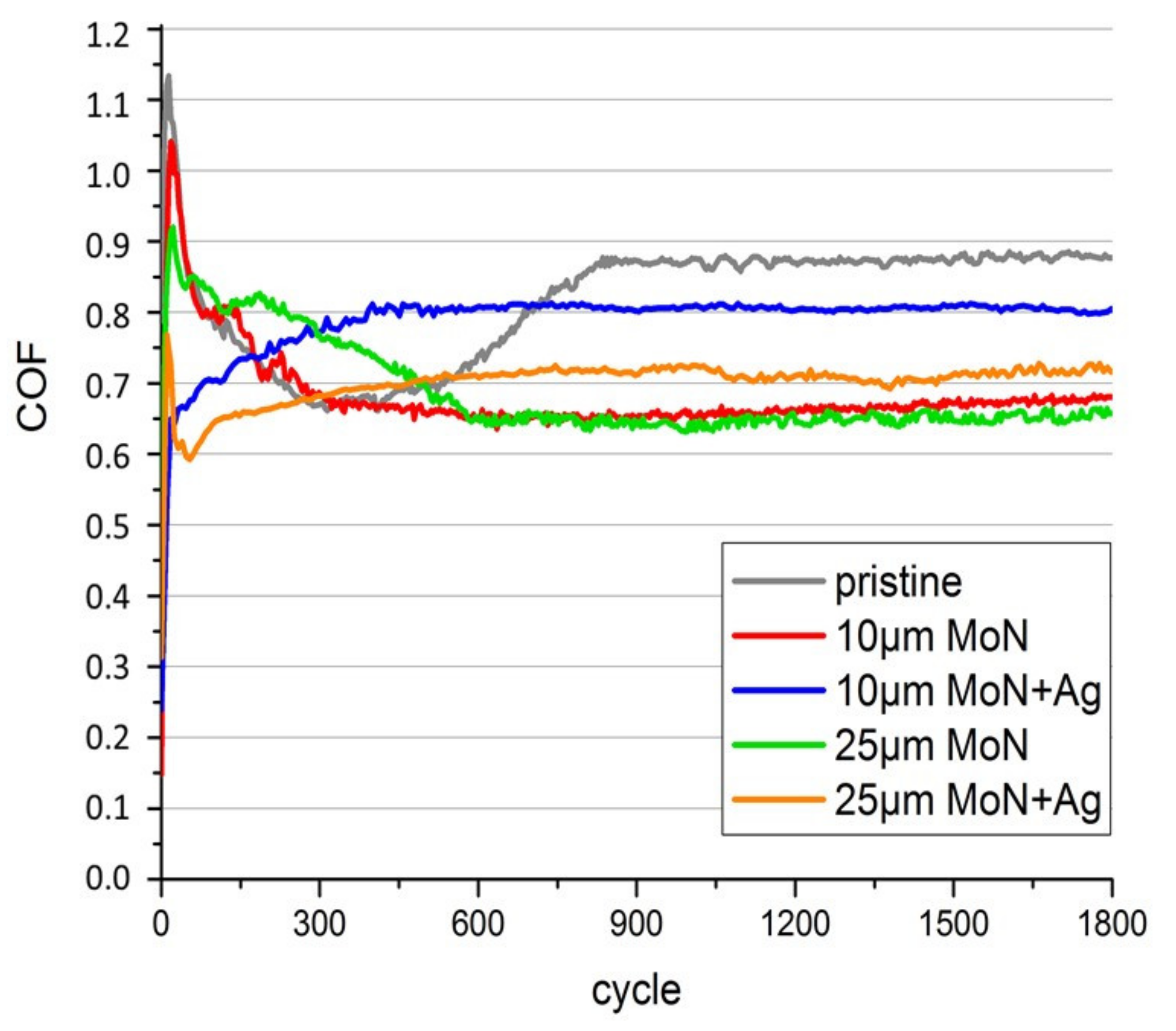
Figure 2 shows exemplary measurements of the coefficient of friction (COF) extracted from the oscillation tribometry. The diagram displays the COF during a measurement period of t = 15 min. The colors refer to the images of Figure 1; the polished surface that acted as the reference is depicted in grey.
In all curves, COF values between 0.6 and 0.9 were found. After a running-in period of a few minutes, we observed quite constant COFs for all surfaces. The MoN film on a pristine surface (grey) exhibited the largest COF of about µ = 0.88. Statistics on a series of similar surfaces led to a confidence interval of µ = 0.87 ± 0.02. For the embossed substrates, a significantly smaller µ ≈ 0.65–0.7 was found, which was a reduction of more than 20% [5]. Considering the surfaces of the silver-containing substrates, values were found that were in-between. As mentioned above, the surface was not completely flat in these cases, leading to a reduction in the COF as well. For the silver-filled 25 µm structures, the effect was more pronounced due to the larger volume of the voids created in the polishing step. The exemplary curves in Figure 2 show that the introduction of the engineered substrates with the subsequent deposition was a practicable way to directly influence the occurring friction forces.
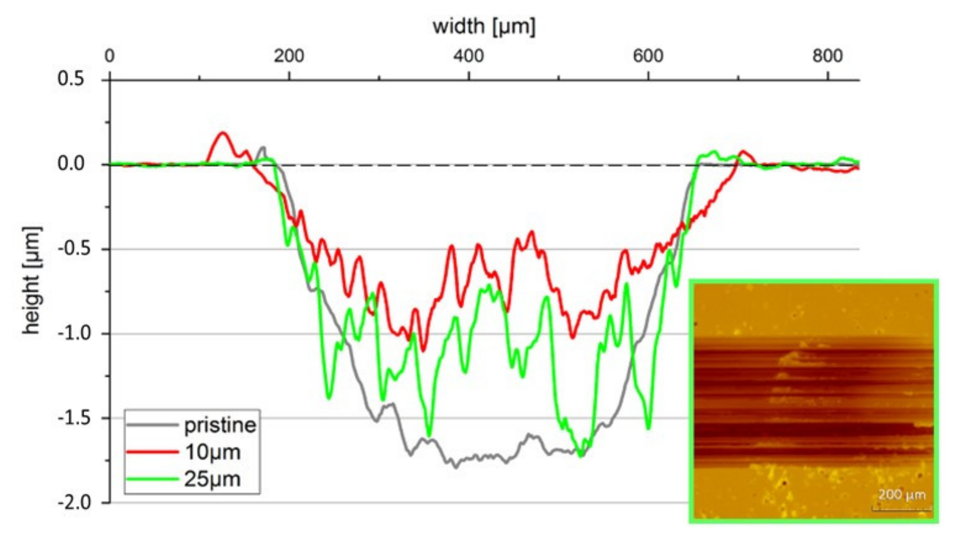
To correlate the wear created during the mechanical load with the observed friction curves, we performed detailed investigations of the corresponding wear tracks. Figure 3 depicts the cross-sections of the wear tracks that were generated during the tribometry process. In all cases, a measurement period of 60 min was chosen to reduce the influence of the variations that occurred during the initial part of the wear process.
After this intense mechanical treatment, the surfaces were analyzed by white-light interferometry and a cross-sectional profile was extracted perpendicular to the track. The presented profiles were horizontally averaged over 800 µm.
The graph in Figure 3 displays the results obtained from the microembossed surfaces; an untreated reference is shown in grey. We observed wear tracks with a width of about 450 µm and a maximum depth of up to 1.7 µm. As the thickness of the MoN films was 2.2 ± 0.1 µm, we could rule out the possibility that the wear process reached the substrate material in all considered cases.
It is important to note that there was a sharp edge of the wear track toward the unmodified surface beneath. We did not find any substantial modifications outside the wear track.
Figure 3 clearly shows that the depth of the wear track—and, therefore, the wear volume—was significantly reduced when embossed substrates were used. The comparison of the cross-sections provided a reduction in the wear volume for the 25 µm imprints (green) of about 20% and for the 10 µm imprints of close to 50% (red). This confirmed other, previous results [6] and could be explained by the capture of abrasion particles inside the imprints that led to reduced abrasion. Interestingly, the surface containing 25 µm imprints showed the most prominent wear scars with a typical width of 30–50 µm, suggesting that, in this particular case, large abrasion particles also played a role.
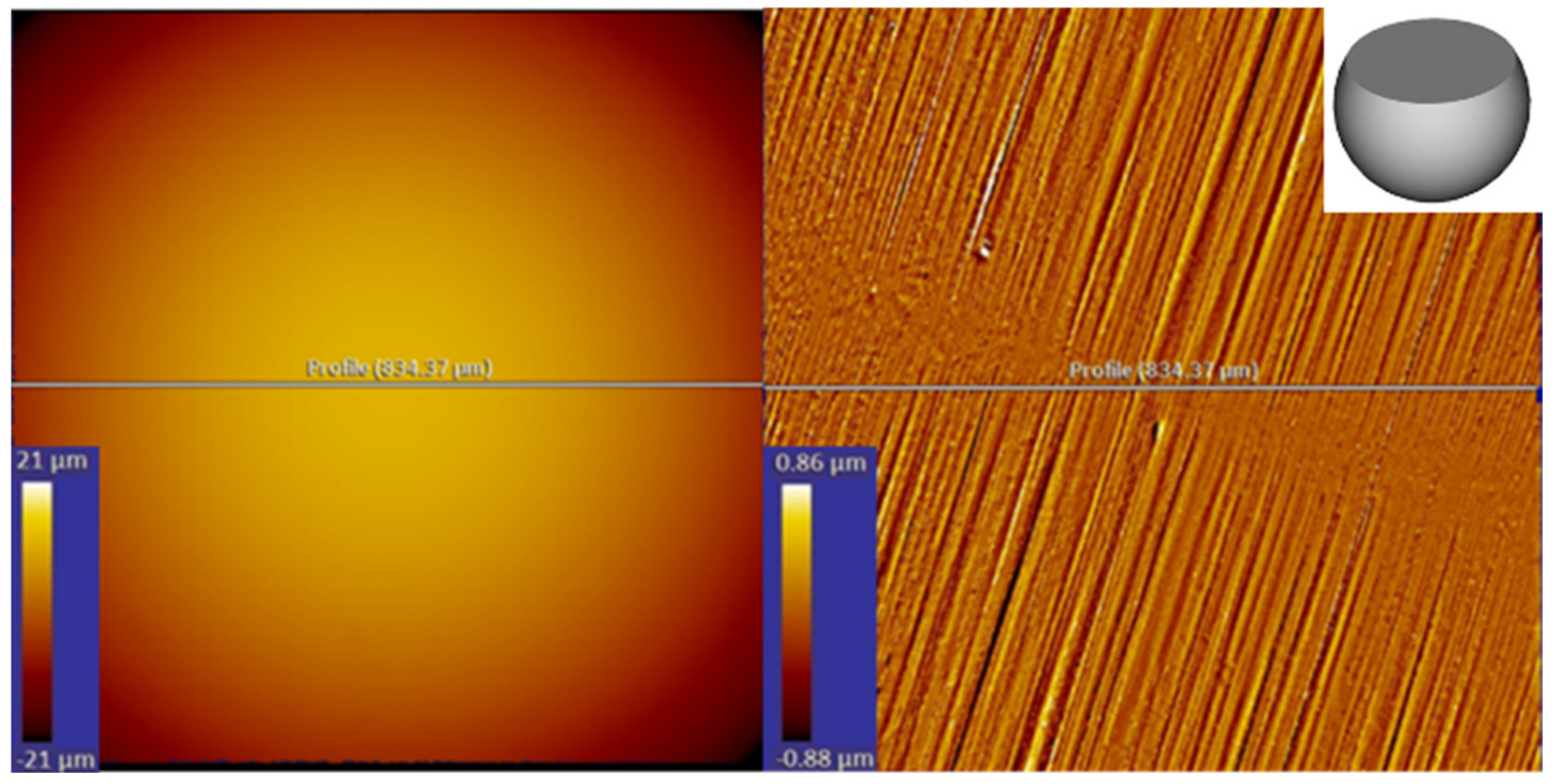
Figure 4 depicts the surface of a counterbody before and after tribological stressing. The spherical surface was worn out due to abrasion so that a flat circular area remained after conditioning. The volume of the missing spherical segment then geometrically determined the counterbody wear volume. The mechanical energy needed for this abrasion process was dependent on the final size of the Fe/FeO abrasion particles because they were crushed down in size after being removed from the counterbody, absorbing more initial energy. However, the energy used to damage the counterbody was estimated to be in the order of 1%–2% of the total energy consumption. The details will be published elsewhere.
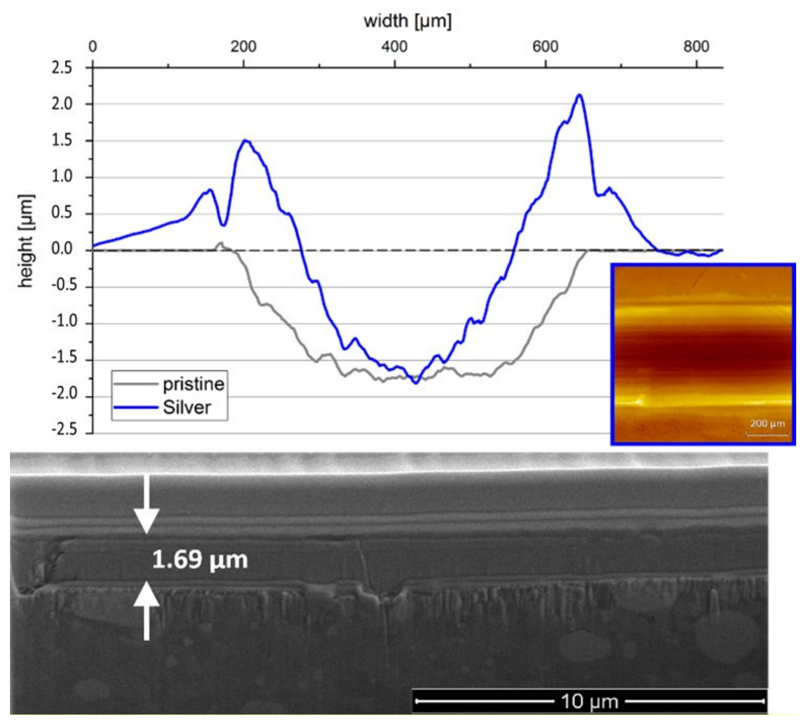
These results were, in the next step, compared with the wear tracks that were generated on the silver-containing surfaces during an equivalent mechanical treatment. Figure 5 shows the respective cross-section of the wear track obtained from a surface with 10 µm silver-filled imprints after a mechanical treatment of 60 min.
When comparing the blue and the grey profiles, significant differences were apparent. Although the blue curve exhibited a similar width and depth of the wear track, there were significant differences when considering the edges of the track. With the blue curve, a prominent elevation of the surface with a height of about 2 µm was found aside the track. This clearly indicated a more complex wear mechanism compared with the other considered cases. To generate this type of surface topography, a certain amount of material was obviously transferred to the rim of the wear track. At the same time, the determination of an abrasion volume as previously achieved was not directly possible.
For that purpose, an FIB cut was prepared inside the wear track that allowed us to image the cross-section of the MoN film via scanning electron microscopy (SEM). We determined the thickness of the remaining MoN layer after the mechanical treatment to be still 1.69 µm. Comparing this number with the depth of the wear track, which could be extracted from Figure 4 to be in the order of 1.5 µm, we could clearly conclude that the depth of the wear track was not solely formed by the abrasion of MoN as seen in all the other investigated surfaces.
The silver content in the voids of the steel substrate obviously led to a plastic deformation of the substrate. The depth of the wear track increased without harming the wear-resistant layer that was pushed into the substrate. As the deformation process consisted of both the compression and displacement of the material, this could also explain the appearance of the bulges aside the wear track. Comparing the remaining thickness of d = 1.69 µm, which had a nominal thickness after deposition of d = 2.2 ± 0.1 µm, we observed an abrasion depth of MoN of about 0.5 µm. This was less than all the other cases discussed before.
4. Discussion
The abrasion volume V—i.e., the loss of MoN—is the quantity that is responsible for the lifetime of the coating. For pristine and embossed surfaces, this is considered to be equivalent to the volume of the wear track. It was directly extracted from the surface topography profiles, as shown in Figure 3.
The addition of silver to the substrate surface led to a more complex scenario because there was a substantial deformation of the surface, including a transfer of material to the rim of the wear track. To extract the volume loss of MoN, we determined the remaining thickness of the (deformed) MoN film in the center of the wear track from the SEM images and considered this thickness to be constant in the whole wear track. This overestimated the wear volume because the abrasion is usually the largest in the center of a track. However, the deformation of the surface led to a larger contact area to the counterbody during the whole test procedure, so the assumption of a constant film thickness was considered to be acceptable.
To find a reasonable description for the performance of the MoN coatings on different substrates, the wear rates—calculated as the wear volume divided by the travelling distance of the normal force times—were plotted versus the friction coefficient µ. The diagram is shown in Figure 6.
The filled symbols in grey, green, red and blue refer to the surfaces investigated in this work; the colors were chosen according to Figure 3 and Figure 4. The open black symbols refer to data from [16]. The dashed line displays the simple model that the abrasion volume was proportional to the friction work that was provided by the tribometer [27]. This mechanical work Wmech could be simply calculated as the friction force F times the sliding distance d, where the friction force F was found by the product of the normal force FN and COF µ: Wmech = FN × µ × d.
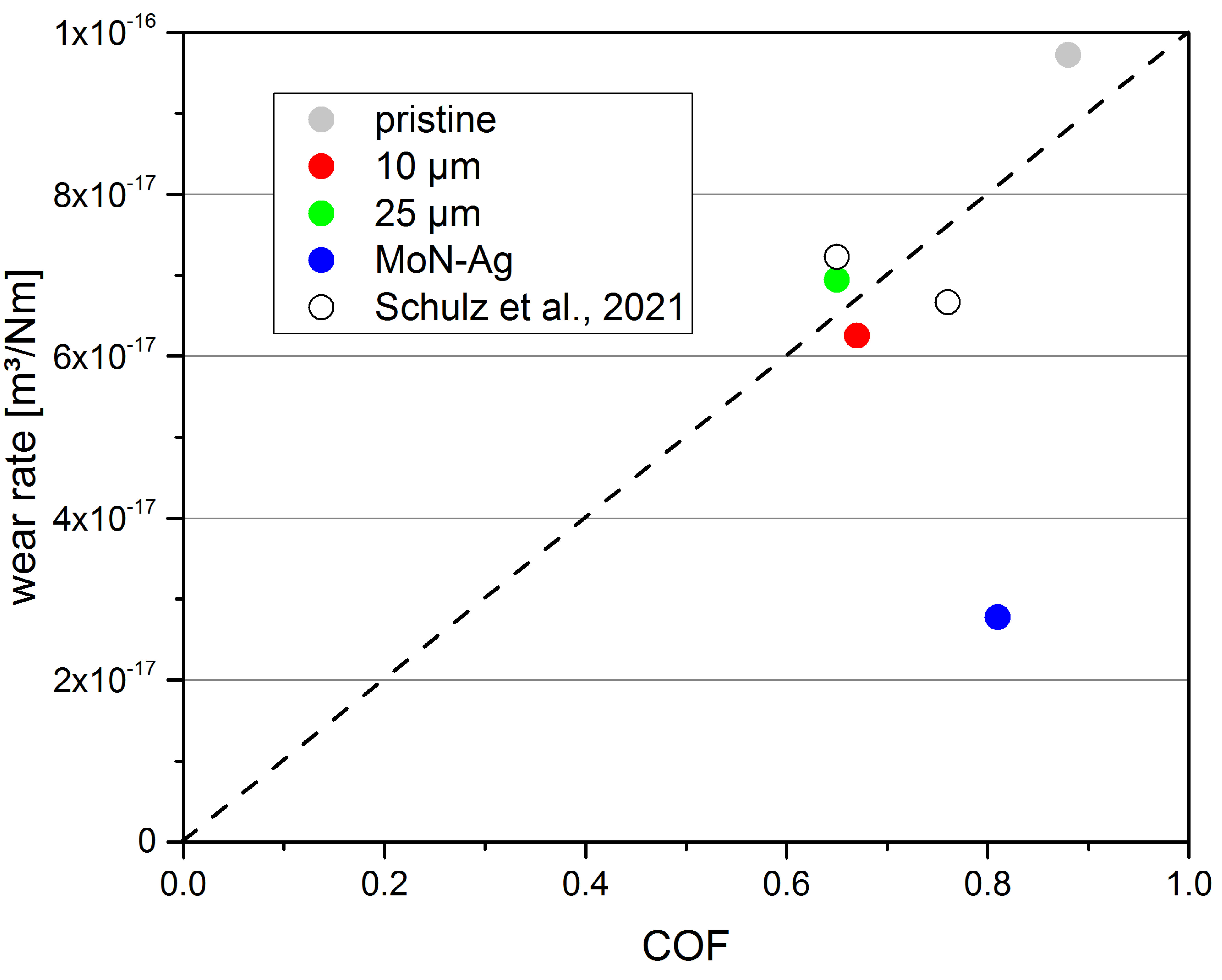
The data of all molybdenum nitride surfaces that were deposited onto the substrates with different topographies (without silver) could be approximated reasonably well by the dashed line. The only datapoint that drastically deviated from this linear relation was the one obtained for the silver-containing substrate (blue), where we found an abrasion rate that was reduced by a factor of about three.
The simplified linear model suggested that the friction work provided during the mechanical testing procedure was responsible for the abrasion. Abrasion particles provided by the 100Cr6 counterbody were the origin of the evolution of the abrasion scars. This was considered to be the dominant mechanism of material removal. If cavities were offered that collected abrasion particles, this process was suppressed. As a consequence, both the COF and the wear volume were significantly reduced in the same way. The ratio of the wear rate and the provided mechanical work remained constant because particle-mediated abrasion was the dominant mechanism.
However, this picture included a number of approximations. An important one was that the surface/volume ratio of the abrasion particles had to be constant to result in a constant contribution of surface energies. This did not hold if the surface had prominent edges or ridges perpendicular to the motion of the counterbody. In this case, significant grooving led to larger abrasion particles and, therefore, larger volumes. However, such surfaces were not included in the data presented in Figure 6.
In the picture of “work” and “energy”, an explanation could be provided for the strong reduction in the wear rate for the silver-containing sample depicted in blue in Figure 6. A severe deformation of the substrate and film material was observed, which led to a substantial transfer of material to the edges of the wear track and to an elevation of the surface. This deformation consumed large parts of the provided mechanical work during testing. As a consequence, much less work remained for the abrasion process; in the considered case, roughly one-third. This indicated that the energy consumption of the deformation process could lead to an increase in the surface lifetime under a mechanical load, at least in the case of applications that did not suffer from deformations of the surface.
5. Conclusions
In this work, we examined the tribological behavior of thin MoN coatings on microengineered steel surfaces. We showed that a modified substrate topography led to MoN surfaces that exhibited strongly reduced friction and wear under dry conditions. The corresponding wear process was particle-mediated abrasion. In more detail, we showed that a reduced COF led directly to a reduction in the observed wear because the provided mechanical work during testing was the governing property for material removal. The introduction of silver to the substrate surface in the form of microislands led to a significantly different wear scenario and a further possible lifetime increase of the coating. A strongly increased deformation of the base material underneath the MoN film was observed, leading to a modified wear track. This deformation consumed large parts of the provided mechanical energy of the friction process. As a consequence, less abrasion was observed. Finally, we can state that a modification to the surface of a substrate on a microscale can be considered to be an efficient tool to control friction and wear on nitride-coated surfaces.
Author Contributions
Conceptualization, W.S. and J.A.; methodology, M.F. and J.A.; validation, F.K., M.B. and M.F.; formal analysis, W.S.; investigation, W.S. and M.B., data curation, W.S. and F.K.; writing—original draft preparation, W.S. and J.A.; writing—review and editing, M.B. and M.F.; visualization W.S. and F.K.; supervision, J.A. All authors have read and agreed to the published version of the manuscript.
Funding
This research received no external funding.
Institutional Review Board Statement
Not applicable.
Informed Consent Statement
Not applicable.
Data Availability Statement
Not applicable.
Acknowledgments
The authors appreciate the support of T. Weidler from Casting Technology Aalen for carrying out the mechanical structuring.
Conflicts of Interest
The authors declare no conflict of interest.
References
- Gassner, G.; Mayrhofer, P.H.; Kutschej, K.; Mitterer, C.; Kathrein, M. Magnéli phase formation of PVD Mo–N and W–N coatings. Surf. Coat. Technol. 2006, 201, 3335–3341. [Google Scholar] [CrossRef]
- Suszko, T.; Gulbiński, W.; Jagielski, J. The role of surface oxidation in friction process on molybdenum nitride thin films. Surf. Coat. Technol. 2005, 194, 319–324. [Google Scholar] [CrossRef]
- Koshy, R.A.; Graham, M.E.; Marks, L.D. Synthesis and characterization of CrN/Mo2N multilayers and phases of Molybdenum nitride. Surf. Coat. Technol. 2007, 202, 1123–1128. [Google Scholar] [CrossRef]
- Rosenkranz, A.; Reinert, L.; Gachot, C.; Mücklich, F. Alignment and wear debris effects between laser-patterned steel surfaces under dry sliding conditions. Wear 2014, 318, 49–61. [Google Scholar] [CrossRef]
- Sube, T.; Kommer, M.; Fenker, M.; Hader, B.; Albrecht, J. Reduced friction on γ-Mo2N coatings deposited by high power impulse magnetron sputtering on microstructured surfaces. Tribol. Int. 2017, 106, 41–45. [Google Scholar] [CrossRef]
- Kommer, M.; Sube, T.; Richter, A.; Fenker, M.; Schulz, W.; Hader, B.; Albrecht, J. Enhanced wear resistance of molybdenum nitride coatings deposited by high power impulse magnetron sputtering by using micropatterned surfaces. Surf. Coat. Technol. 2018, 333, 1–12. [Google Scholar] [CrossRef]
- Amanov, A.; Tsuboi, R.; Oe, H.; Sasaki, S. The influence of bulges produced by laser surface texturing on the sliding friction and wear behavior. Tribol. Int. 2013, 60, 216–223. [Google Scholar] [CrossRef]
- Bathe, R.; Krishna, V.S.; Nikumb, S.K.; Padmanabham, G. Laser surface texturing of gray cast iron for improving tribological behavior. Appl. Phys. A 2014, 117, 117–123. [Google Scholar] [CrossRef]
- Köhn, F.; Schulz, W.; Albrecht, J. Verschleißschichten auf schlauen Substraten-Geschützte Oberflächen mit Eigenschaften nach Maß. Galvanotechnik 2018, 5, 1051–1054. [Google Scholar]
- Andersson, P.; Koskinen, J.; Varjus, S.; Gerbig, Y.; Haefke, H.; Georgiou, S.; Zhmud, B.; Buss, W. Microlubrication effect by laser-textured steel surfaces. Wear 2007, 262, 369–379. [Google Scholar] [CrossRef]
- Rapoport, L.; Moshkovich, A.; Perfilyev, V.; Lapsker, I.; Halperin, G.; Itovich, Y.; Etsion, I. Friction and wear of MoS2 films on laser textured steel surfaces. Surf. Coat. Technol. 2008, 202, 3332–3340. [Google Scholar] [CrossRef]
- Oksanen, J.; Hakala, T.J.; Tervakangas, S.; Laakso, P.; Kilpi, L.; Ronkainen, H.; Koskinen, J. Tribological properties of laser-textured and ta-C coated surfaces with burnished WS2 at elevated temperatures. Tribol. Int. 2014, 70, 94–103. [Google Scholar] [CrossRef]
- Pacella, M.; John, M.G.J.S.; Dolatabadi, N.; Badiee, A. Microhardness and wear behaviour of polycrystalline diamond after warm laser shock processing with and without coating. Int. J. Refract. Met. Hard Mater. 2019, 82, 215–226. [Google Scholar] [CrossRef]
- Haus, L.; Wildfeuer, M.; Grochowski, J.-E.; Wöckel, J.; Müller, M.; Köhn, F.; Schulz, W.; Wüstefeld, C.; Rafaja, D.; Albrecht, J. Wear properties of carbon-rich tungsten carbide films. Wear 2022, 488–489, 204146. [Google Scholar] [CrossRef]
- Köhn, F.; Sedlmajer, M.; Albrecht, J.; Merkel, M. Additive Manufacturing of Tungsten Carbide Surfaces with Extreme Wear Resistivity. Coatings 2021, 11, 1240. [Google Scholar] [CrossRef]
- Schulz, W.; Köhn, F.; Kolb, D.; Balzer, M.; Riegel, H.; Albrecht, J. Controlling friction and wear with anisotropic microstructures in MoN coated surfaces. Trib. Lett. 2021, 59, 152. [Google Scholar] [CrossRef]
- Fenker, M.; Balzer, M.; Kellner, S.; Polcar, T.; Richter, A.; Schmidl, F.; Vitu, T. Formation of Solid Lubricants during High Temperature Tribology of Silver-Doped Molybdenum Nitride Coatings Deposited by dcMS and HIPIMS. Coatings 2021, 11, 1415. [Google Scholar] [CrossRef]
- Anitha, V.; Major, S.; Chandrashekharam, D.; Bhatnagar, M. Deposition of molybdenum nitride thin films by r.f. reactive magnetron sputtering. Surf. Coat. Technol. 1996, 79, 50–54. [Google Scholar] [CrossRef]
- Yang, S.; Li, X.; Cooke, K.; Teer, D. A study of TiMoN nano-multilayer coatings deposited by CFUBMSIP using DC and HIPIMS power. Appl. Surf. Sci. 2011, 258, 2062–2067. [Google Scholar] [CrossRef]
- Zhu, X.; Yue, D.; Shang, C.; Fan, M.; Hou, B. Phase composition and tribological performance of molybdenum nitride coatings synthesized by IBAD. Surf. Coat. Technol. 2013, 228, S184–S189. [Google Scholar] [CrossRef]
- Gilewicz, A.; Warcholinski, B.; Murzynski, D. The properties of molybdenum nitride coatings obtained by cathodic arc evaporation. Surf. Coat. Technol. 2013, 236, 149–158. [Google Scholar] [CrossRef]
- Balzer, M.; Fenker, M. Three-dimensional thickness and property distribution of TiC films deposited by DC magnetron sputtering and HIPIMS. Surf. Coat. Technol. 2014, 250, 37–43. [Google Scholar] [CrossRef]
- Bittner, A.; Schneider, M.; Schmid, U. Impact of sputter deposition parameters on molybdenum nitride thin film properties. J. Micromech. Microeng. 2015, 25, 074001. [Google Scholar]
- Mei, H.; Zhao, S.; Wu, Z.; Dai, W.; Wang, Q. Effect of nitrogen partial pressure on microstructure and mechanical properties of Mo-Cu-V-N composite coatings deposited by HIPIMS. Surf. Coat. Technol. 2017, 329, 68–76. [Google Scholar] [CrossRef]
- Kouznetsov, V.; Macák, K.; Schneider, J.M.; Helmersson, U.; Petrov, I. A novel pulsed magnetron sputter technique utilizing very high target power densities. Surf. Coat. Technol. 1999, 122, 290–293. [Google Scholar] [CrossRef]
- Pettersson, U.; Jacobson, S. Tribological texturing of steel surfaces with a novel diamond embossing tool technique. Tribol. Int. 2006, 39, 695–700. [Google Scholar] [CrossRef]
- Fouvry, S.; Liskiewicz, T.; Kapsa, P.; Hannel, S.; Sauger, E. An energy description of wear mechanisms and its applications to oscillating sliding contacts. Wear 2003, 255, 287–298. [Google Scholar] [CrossRef] [Green Version]
Figure 1.
Surface topography of MoN films deposited onto microengineered surfaces obtained by white-light interferometry. The left column displays the MoN surface on top of embossed substrates created with 10 µm (top, red) and 25 µm (bottom, green) stamps. The right column refers to equivalently embossed substrates where the imprints of 10 µm (top, blue) and 25 µm (bottom, orange) were filled with silver before the deposition of MoN. The inset in the top left corner displays the bare substrate after embossing.

Figure 2.
COF extracted from oscillation tribometry over a period of t = 15 min. The grey curve provides data of the reference surface. Red and green refer to the MoN surfaces on embossed substrates; blue and orange contain silver-filled cavities.
Figure 2.
COF extracted from oscillation tribometry over a period of t = 15 min. The grey curve provides data of the reference surface. Red and green refer to the MoN surfaces on embossed substrates; blue and orange contain silver-filled cavities.

Figure 3.
Cross-sectional profiles of the wear tracks after oscillation tribometry. The surfaces on embossed substrates (red, green) exhibited a significantly reduced wear volume compared with the pristine case (grey). The inset shows the surface topography of the wear track from the 25 µm imprints.

Figure 4.
Surface topography of an untreated, spherical counterbody with a surface quality of G20 (left) and a counterbody after being used in a tribological experiment (right).
Figure 4.
Surface topography of an untreated, spherical counterbody with a surface quality of G20 (left) and a counterbody after being used in a tribological experiment (right).

Figure 5.
(Top) Cross-sectional profile of the wear track on a silver-containing surface (10 µm, blue) in comparison with a reference (grey). The inset shows the corresponding wear track. (Bottom) Cross-section of the surface inside the wear track analyzed using a focused ion beam (FIB) cut and scanning electron microscopy. The arrows mark the remaining MoN layer.

Figure 6.
Calculated wear rates versus the corresponding coefficient of friction (averaged after running-in) for the surfaces presented in this work (colors) and data from Schulz et al., 2021 [16]. The dashed line refers to the model that the provided work in the testing routing is proportional to the abrasion volume.

Publisher’s Note: MDPI stays neutral with regard to jurisdictional claims in published maps and institutional affiliations. |
© 2022 by the authors. Licensee MDPI, Basel, Switzerland. This article is an open access article distributed under the terms and conditions of the Creative Commons Attribution (CC BY) license (https://creativecommons.org/licenses/by/4.0/).
Share and Cite
MDPI and ACS Style
Schulz, W.; Köhn, F.; Balzer, M.; Fenker, M.; Albrecht, J. Properties of Wear-Resistant MoN Films on Microengineered Substrates. Coatings 2022, 12, 1232. https://doi.org/10.3390/coatings12091232
AMA Style
Schulz W, Köhn F, Balzer M, Fenker M, Albrecht J. Properties of Wear-Resistant MoN Films on Microengineered Substrates. Coatings. 2022; 12(9):1232. https://doi.org/10.3390/coatings12091232
Chicago/Turabian StyleSchulz, Wadim, Florian Köhn, Martin Balzer, Martin Fenker, and Joachim Albrecht. 2022. "Properties of Wear-Resistant MoN Films on Microengineered Substrates" Coatings 12, no. 9: 1232. https://doi.org/10.3390/coatings12091232
Note that from the first issue of 2016, this journal uses article numbers instead of page numbers. See further details here.