
Additive Manufacturing of Tungsten Carbide Surfaces with Extreme Wear Resistivity


1
Research Institute for Innovative Materials (FINO), Aalen University, Beethovenstr. 1, D-73430 Aalen, Germany
2
Institute for Virtual Product Development (ZVP), Aalen University, Beethovenstr. 1, D-73430 Aalen, Germany
*
Author to whom correspondence should be addressed.
Coatings 2021, 11(10), 1240; https://doi.org/10.3390/coatings11101240
Submission received: 19 August 2021
/
Revised: 27 September 2021
/
Accepted: 9 October 2021
/
Published: 13 October 2021
(This article belongs to the Special Issue Advances in Deposition and Characterization of Hard Coatings)
Abstract
:Steel surfaces have been coated with Co-based tungsten carbide (WC) in an additive printing process. This process leads to compact and extremely mechanically stable surfaces. We performed tribological measurements using WC counter bodies under dry conditions and severe mechanical load. Low coefficients of friction, even for rough surfaces, were found and the resulting wear rates were extraordinarily small, even when compared to high-quality PVD film with a similar composition. These findings suggest a wide field of application for this novel preparation process for wear-resistive surfaces.
1. Introduction
Additive manufacturing (AM) is a powerful way to produce parts with complex geometry without special tooling. It is very well suited for highly sophisticated functional parts, such as topology optimization, lightweight construction and cooling channels in injection moulds [1,2,3].
AM is typically classified in terms of its applications as rapid prototyping, rapid tooling and rapid manufacturing. Further classifications can be determined with respect to the material (e.g., plastic, metal, ceramic) or the physical/chemical binding mechanism used in the process. The so-called laser-powder bed fusion (L-PBF) process is a powder bed-based AM process and creates metal components by selectively exposing successive powder layers to a laser beam as the driving force for local solidification [4].
It has been demonstrated that the mechanical properties of almost all available materials are anisotropic and depend on the position and orientation in the installation space [5,6]. Due to the high energy input from the laser on a locally very small area and the rapid cooling, high temperature gradients occur that lead to residual stress and substantial deformations. To counteract this, the L-PBF process requires, among other things, support structures during the process and heat treatment of the components post-process [7,8]. Despite these challenges, many small series and prototypes show that the L-PBF process has established itself with standard materials such as AlSi10Mg or 1.2709 tool steel [9].
Surfaces that are exposed to mechanical forces frequently require additional treatments or coatings to meet the demands of wear resistance and achieve reasonable life times. Typical processes that are used for machinery components and/or tools are plasma nitriding [10,11], electroplating and vacuum deposition of transition metal nitrides or carbides. Transition metal compounds such as CrN [12], TiAlN [13], MoN [14,15] and WC [16,17] exhibit outstanding resistances against wear. However, stoichiometric and adhesive coatings often require complex vacuum deposition techniques, which are associated with long deposition times and relatively small thicknesses of typically less than 10 microns. To achieve large adhesion forces, complex preparation procedures have to be carried out in most cases.
However, there are a number of applications, such as mechanical seals, that require much thicker WC layers of 1–3 mm. In these applications, sintered blanks are usually soldered, pressed or glued onto a base body.
In this work, we introduce an additive manufacturing process for the production of wear-resistive tungsten carbide coatings. Investigations have shown that conventional sintered materials, such as WC, can also be used as materials for the L-PBF process to a certain extent [18]. When processing WC/Co in this process, local under-carbonization may occur, resulting in undesirable η-phase and W2C [19]. Studies have also been carried out on the production of complete cutting tools from WC/Co [20]. Individual wear layers can be built in different layer thicknesses. There are also initial successes in coating stainless steels with carbide using L-PBF processes [21].
The analysis of the wear resistivity of the prepared surfaces with and without additional surface treatment was undertaken using quantitative oscillation tribometry. In particular, wear tests under dry conditions against WC/Co counter bodies were performed. Friction and wear were analysed and compared to results obtained with PVD-deposited films.
2. Experimental
The specimens were created with a selected laser-melting set-up, an SLM 280 HL (SLM Solution Group AG, Lübeck, Germany), using the L-PBF process. As a laser source, a 400 W Yb-fiber-laser was used that works with a minimum spot diameter of about 80 µm and argon as the process gas. The build space is cylindrical with a diameter of 90 mm and a height of 100 mm. The preheating temperature of the build platform was T = 200 °C.
For the L-PBF process, a standard WC/Co powder “Amperit 526.059” was used. This powder is used in flame or plasma spraying and offers adequate properties including flowability and grain size, as required in the L-PBF process. The powder was in an agglomerated and partially sintered state, and the Co content was 17%. According to the manufacturer’s specification, the grain distribution was D90 of 28 µm, D50 of 18 µm and a D10 of 12 µm.
The parameters for the L-PBF process were selected according to a parameter study [21]. A stainless, austenitic, chromium–nickel–molybdenum steel was used for the substrate plate. It was Fe-based with Cr 17%, Ni 10%, Mo 2%, Mn 2%, Si 1%, P 0.045%, S 0.03 C 0.03% and N 0.1% (1.4404/316L/A276).
The volumetric energy density (VED (Ev (J/mm3))) was calculated from the laser power P (J/s), scanning speed v (mm/s), line distance d (mm) and layer thickness h (mm) by
The selected parameters (shown in Table 1) led to a VED of 444 J/mm3. The checkerboard pattern was chosen to reduce residual stresses in the manufacturing process.
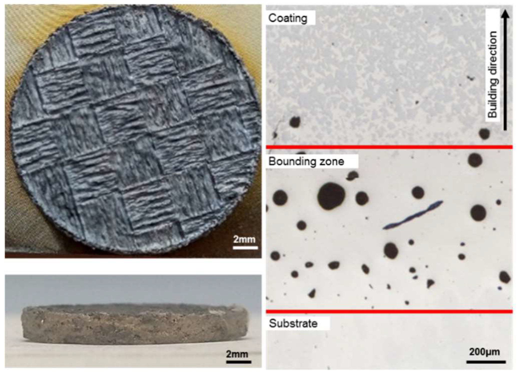
During the additive manufacturing process, three zones are typically formed, and they were also found in the process of this work. The substrate zone is the base material; e.g., 1.4404 stainless steel. In the boundary zone, an intermixing of the base material and the coating material was observed. Finally, close to the materials’ surface (coating zone), only WC/Co could be found [21]. A cross-section of one the specimens revealed the three zones, as depicted in Figure 1.
Since wear-resistive WC/Co surfaces are frequently prepared as PVD coatings, we compared our samples to PVD-coated steel surfaces. The PVD films were prepared by magnetron sputtering of WC/Co targets in an acetylene/argon atmosphere. Details of the preparation can be found elsewhere [17].
Both the 3D-printed surfaces and the PVD films were analysed by X-ray fluorescence analysis using a FischerScope X-ray XAN 120 (Helmut Fischer GmbH, Sindelfingen, Germany) to obtain the elemental composition. In the case of the additive manufactured specimen, a Co content of 13% was found, which was close to the value of 12% found for the PVD film. This means that both surfaces were comparable. The fact that the Co content of the 3D-printed sample was smaller than the nominal Co content of the powder was related to the production process.
The 3D-printed specimens with typical diameters of 20 mm and heights of 3 mm were then used for the analysis of the tribological properties. For preparation purposes, the specimens were oversized in height by 2 mm. The wear resistivity of the surfaces was investigated by oscillation tribometry using an Optimol SRV 3 tribometer (Optimol Instruments Prüftechnik GmbH, München, Germany). Since pairs of tungsten carbide-coated surfaces are frequently used in technical applications, such as rotating mechanical seals, all experiments were performed with WC/Co counter bodies. We used WC/Co balls with diameters of 10 mm under an outstandingly large mechanical load of FN = 50 N without lubricant in order to investigate the behaviour of the surfaces under severe wear conditions. A further increase of friction and wear was realized through the choice of a small oscillation frequency of f = 2 Hz with a corresponding stroke of 1 mm. The topography of the generated wear scars was quantitatively analysed with high spatial resolution using white-light interferometry in combination with classical light microscopy.
From these experiments, the coefficients of friction (COFs) and wear rates were extracted, correlated with the microstructure of the wear scar and compared to results that were obtained from the analysis of WC/Co surfaces that were produced by physical vapour deposition (PVD) of WC on steel (1.3343).
3. Results
A typical printed WC/Co specimen produced in the L-PBF process is depicted in Figure 1. In the printed state, a pronounced checkerboard pattern can be seen on the surface (top left), which was used to minimize the stress distribution in the material. The right panel depicts the cross-section where the three zones mentioned before can be clearly identified [21]. In the bounding zone, the image shows a high density of pores. This was due to the high energy input into the stainless steel substrate plate. The energy density of 444 J/mm3 used for printing WC/Co was more than six times higher than typical parameters used for stainless steel. In contrast to Gütlein [21], there was no intermixing of stainless steel and WC/Co in the bounding zone. Here, it only consisted of stainless steel. In the upper coating zone, the two components of the WC/Co material can be identified: tungsten carbide is dark grey and the cobalt matrix is light grey.
Figure 1 shows that the experimental parameters used allowed the attainment of the crucial goal; namely, the formation of a compact material without cracks and pores. Here, the combination of laser irradiation and substrate preheating had to supply enough energy to realize a complete embedding of WC into the Co binder phase, as shown in previous work [18]. In this study, a laser fluence of 267 J/mm3 in combination with a preheating temperature of 650 °C was used to produce a compact material. Owing to an increase of laser power to 444 J/mm3 in this work, it was possible to reduce the preheating temperature to 200 °C compared to 650 °C in previously published results [18,20]. As result, we found that the produced microstructure of the coating above the boundary zone was basically free of cracks and pores, as can be seen in the micrograph in the right part of Figure 1.
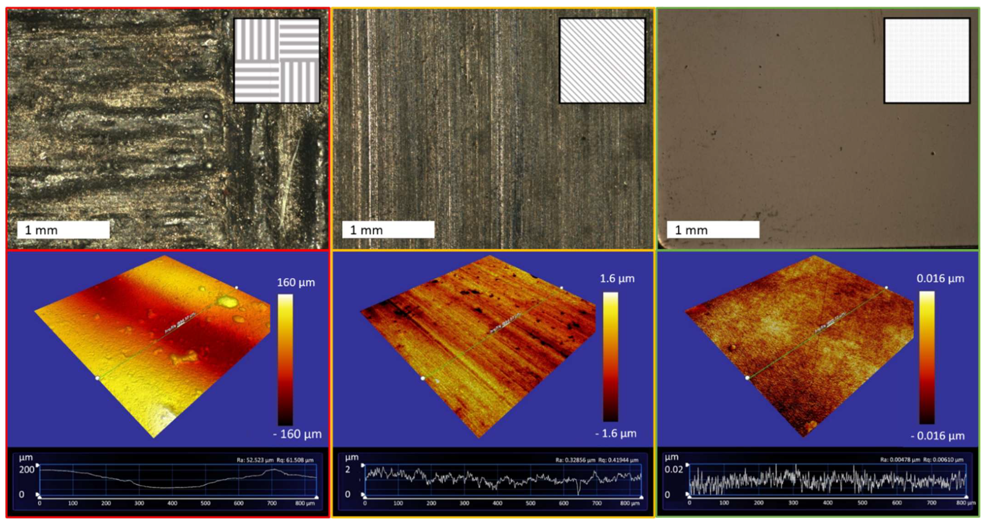
Figure 2 focuses on the surface of the manufactured material before and after additional mechanical processing. For comparison, results obtained with a PVD-coated surface are included as well. The images depict the topographies of three different tungsten carbide surfaces investigated in this work. In the top row, optical micrographs show an as-manufactured surface (left), a mechanically treated surface (centre) and, for comparison, a PVD deposited film (right). The bottom row displays corresponding surface data obtained by white-light interferometry using a ZYGO ZeGage-0100. Note that the z-scale of the interferometry data has been magnified stepwise by a factor of 100 from left to right.
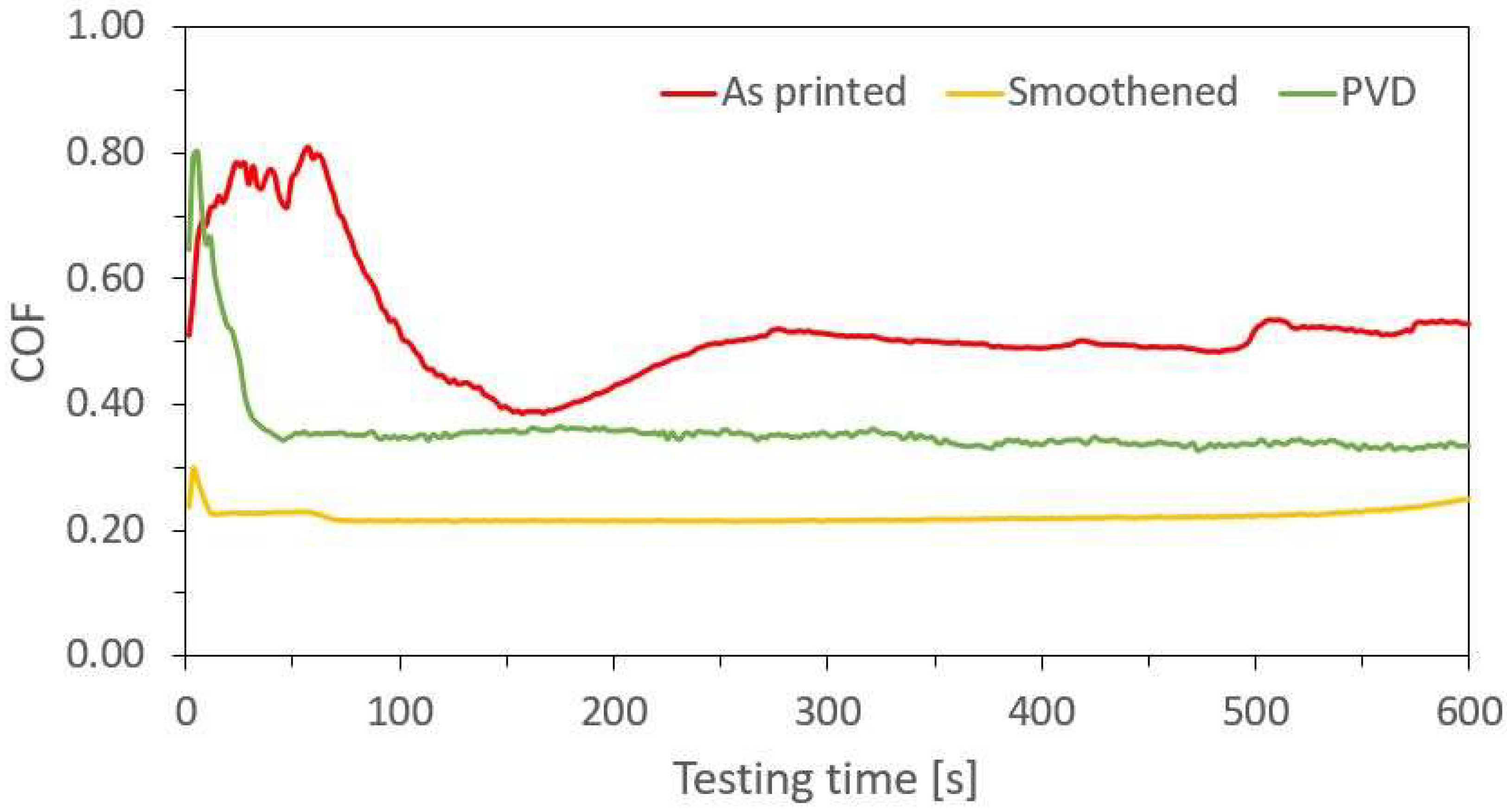
All three surfaces were mechanically analysed by performing oscillation tribometry with WC/Co counter bodies under dry conditions in a vertical direction to the linear structures. Figure 3 shows the coefficients of friction (COFs) obtained under an extremely high load of FN = 50 N and an oscillation frequency of 2 Hz. The maximum relative velocity was 6 mm/s. The parameters, in particular the small velocity, were chosen with the aim of causing the utmost damage to the surface.
The COFs found for the three considered surfaces obtained using a 10 min testing protocol showed dramatically different values. The as-manufactured surface exhibited with µ = 0.5 an astonishing small COF considering the extremely high roughness value of this surface. For the mechanically treated surface, we obtained µ = 0.22 and, for the PVD layer, µ = 0.35. The fact that the printed and mechanically treated surface exhibited less friction than the extremely smooth PVD layer was somewhat surprising at this point. An additional feature was the significant reduction of the “noise” of the friction curves. The as-printed surface showed large variations in the COF value: a more or less constant value of µ = 0.5 was found after t = 300 s but jumps of the order of 10% still occurred afterwards. The PVD curve (green) showed fewer fluctuations; however, the curve was still noisy on short time scales. The most constant behaviour was found for the orange curve (mechanically treated surface) for which the COF was basically stable.
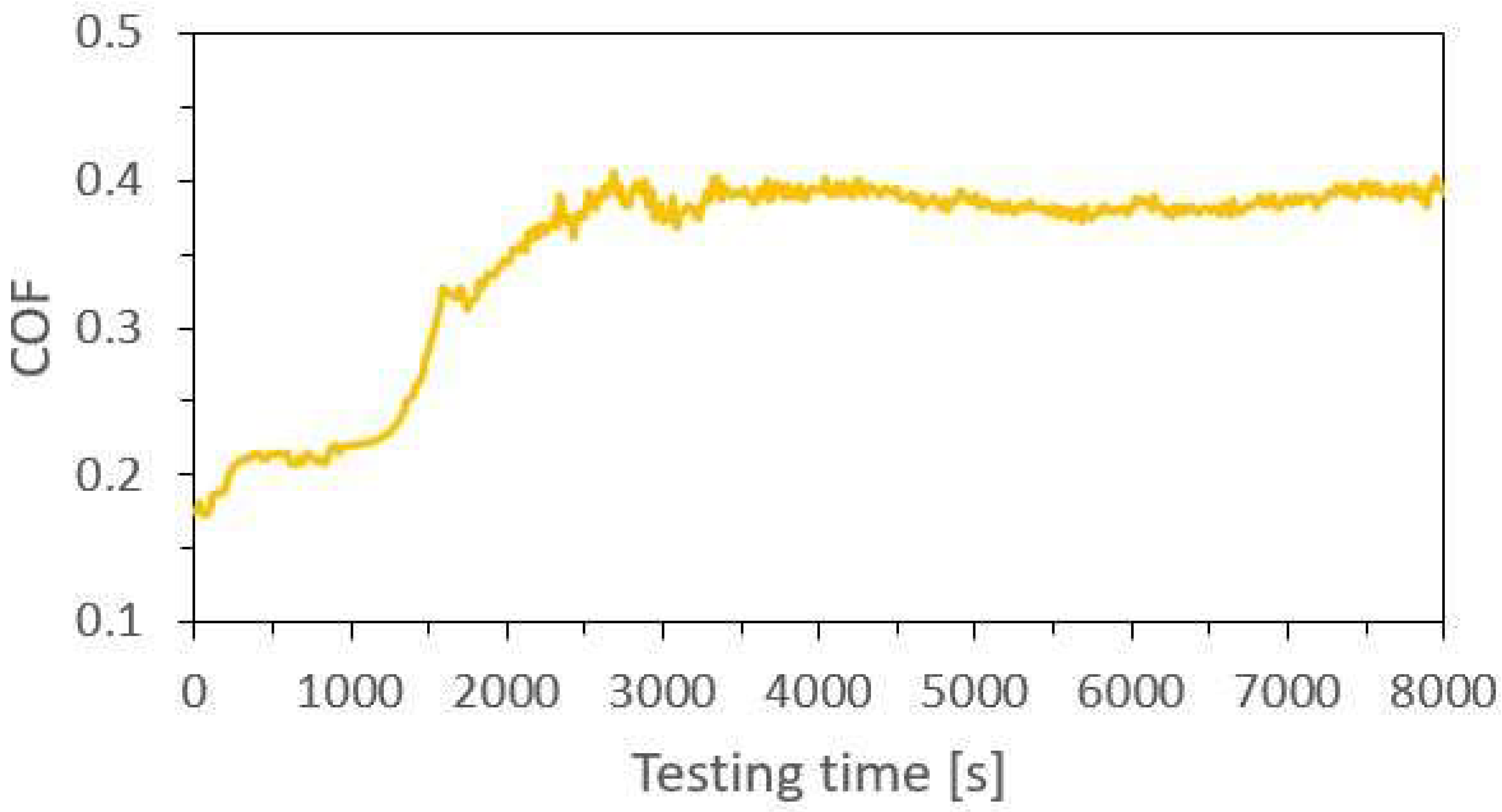
An initial attempt to extract the corresponding wear from these tribology measurements finally failed for all surfaces of the printed material because the wear volume was too small to separate it from the surface roughness. As a consequence, we increased the testing time from 600 to 8000 s. The corresponding COF curve for the mechanically treated surface is depicted in Figure 4.
The extended duration of the testing period led to extended results. After a brief initial period, the constant value of µ = 0.22 was reproduced from Figure 3. Then, after t = 1500 s, an increase in the COF set in that finally led to a second plateau at µ = 0.38, which corresponded nicely to the value that was found for the PVD-coated surface.
The wear scar produced within this severe treatment was finally pronounced enough to allow the determination of wear volumes and a comparison between additionally manufactured surfaces and PVD coatings.
The direct comparison of the results obtained for 3D-printed WC/Co surfaces and the thin PVD coatings after similar treatment was difficult. Therefore, we compared the mechanical effort that was required to generate a certain amount of damage. We performed two experiments under the same tribometric conditions with the goal of removing the same amount of material from the wear track. The results are shown in Figure 5.
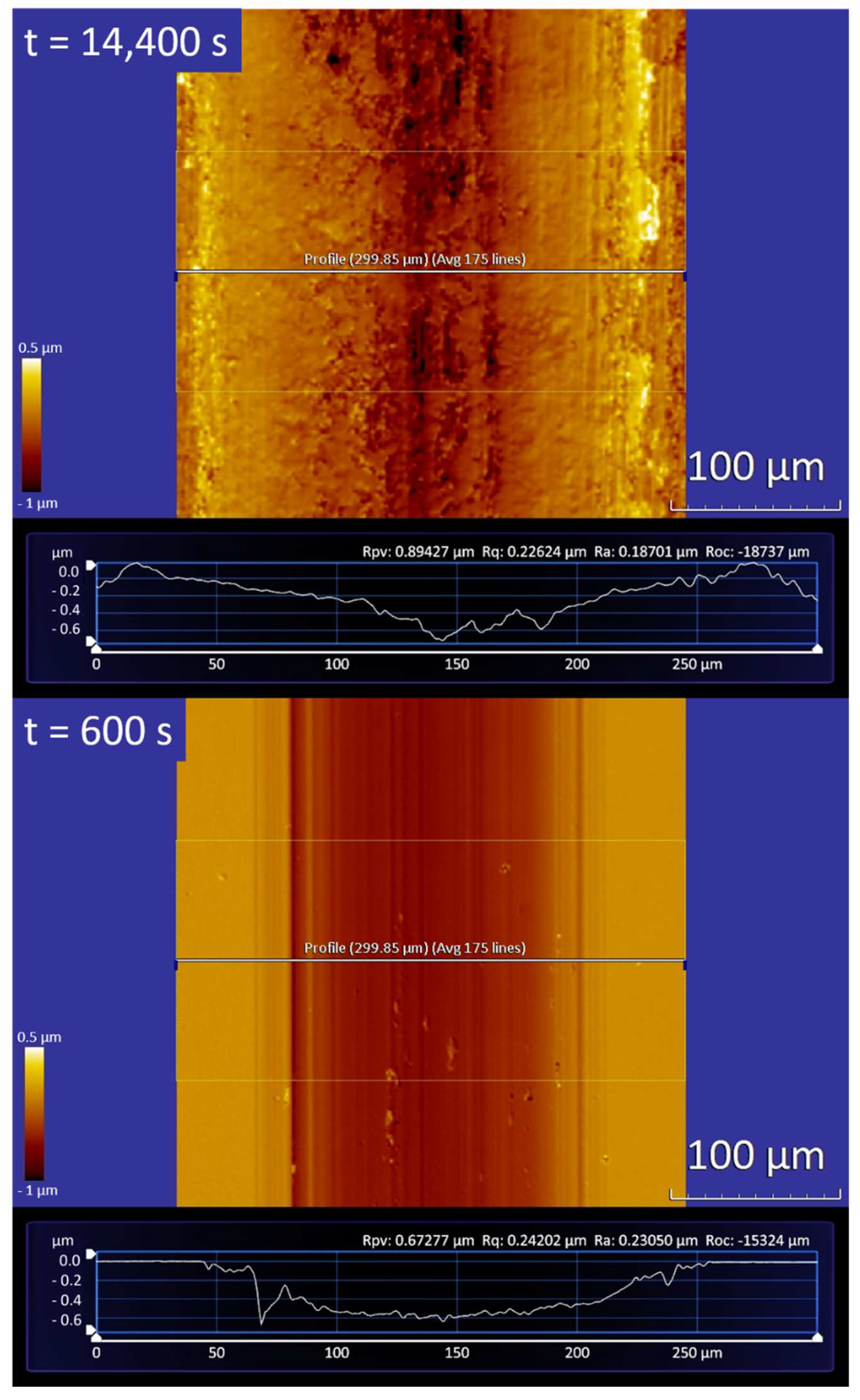
Both wear scars approximately exhibited a cross-section that referred to the negative form of the counter body. The width of the scar from the 3D-printed surface was, with d = 250 µm, approximately 20% broader than the one in the PVD coating. Therefore, the average depth was, with 0.3 µm (maximum depth: 0.43 µm), slightly smaller in the 3D-printed surface than the PVD coating with 0.41 µm (maximum depth: 0.59 µm). In both cases, we found an abrasion volume of V = 80,000 ± 10,000 µm3.
In order to realize the equivalent damage to the 3D-printed coating, the surface was exposed to the same tribological parameters as above, but now for 14,400 s instead of 600 s. Assuming constant wear rates, this led to the conclusion that the wear rate of the 3D-printed WC/Co surface on stainless steel was 24 times smaller than the one found for the high-quality PVD-coated sample.
4. Discussion
First, we consider the friction forces against tungsten carbide counter bodies under dry conditions. Surprisingly, the measured coefficients of friction did not increase with increasing surface roughness as expected. In particular, the mechanically treated 3D-printed surface exhibited the lowest COF of µ = 0.2 among all investigated surfaces, even smaller than a high-quality PVD film.
An explanation can be found when considering the topography of the mechanically treated surface. Here, grinding grooves are present that generate an anisotropic surface structure on the specimen after mechanical processing. It is well-known that appropriate surface texturing can efficiently reduce both mechanical wear and the coefficient of friction in dry friction contacts [22,23,24]. In the case of coated surfaces on micropatterned substrates, a reduction of the COF of up to 30% is found [14]. The functional principle at hand is the trapping of the friction particles in the structures, whereby they are removed from the contact and do not participate further as third bodies in the wear process. The prerequisite for this is that the structures are adapted to the dimensions of the particles in order to be able to absorb and retain them.
The results obtained for the mechanically treated WC/Co surface show that the effect of surface microstructures was even more pronounced. The COF initially obtained of µ = 0.22 (Figure 3, yellow curve) was only found up to a testing time of about 1500 s. This period was followed by a transitional area with a steadily increasing coefficient of friction, in which these structures were removed slowly due to abrasion, and a state of higher areal contact between the friction partners occurred. After 2300 s to 8000 s, a third area followed with a static coefficient of friction of about µ = 0.38, which was considered to describe the friction for surfaces without particular microstructures since abrasion had removed them. Here, surface structures completely disappeared and full contact between the friction partners had been established. The wear-reducing effect of the surface structuring was absent. This interpretation was supported by µ = 0.35, which was found in the case of the extremely smooth PVD film with a roughness Ra below 0.005 µm and which was also considered as flat contact.
The non-treated 3D-printed surface showed the highest friction value, although this sample also had an obvious structuring. However, the dimensions of these structures were very large and thus not suitable for capturing and storing the particles that were created. Thus, the coarse structuring actually only caused an increased local Hertzian pressure during the frictional contact, which promotes the generation of friction particles and thus keeps wear and the friction coefficient high. In this status, it was assumed that, after the structures were removed, the coefficient of friction would decrease and also approach a value of 0.35 to 0.40.
An interesting fact is provided by the analysis of the wear scars found in the mechanically treated surface and the PVD film. Although the COFs found were very similar, we found a dramatic difference in the wear rates that occurred. Starting with the volume of the two wear scars in Figure 5 of about V = 80,000 µm3, we can easily calculate the wear rates that occurred. For a normal force of FN = 50 N and an oscillation frequency of 2 Hz, we end up with a wear rate of about 60–70 × 10−17 m3/Nm, which is comparable with results found for highly wear-resistive PVD coatings, like MoN on steel, for which Kommer et al. reported 50–100 × 10−17 m3/Nm [15]. The surprising result arose from the wear scar that was generated in the 3D-printed surface. Here, an equivalent consideration provides a wear rate of 2.8 × 10⁻¹⁷ m3/Nm, which is more than one order of magnitude smaller than that known for high-quality PVD films under heavy loads. One of the reasons for this striking difference was a difference in the Hertzian pressure of the contact. In the case of the sputtered film, the mechanical properties of the surfaces were strongly influenced by the “soft” steel substrate underneath. The large normal force of FN = 50 N led to a significant deformation of the film and substrate that strongly affected friction and wear.
However, taking into account the fact that the additive manufactured coatings analysed in this work had typical thicknesses of several millimetres, it might be reasonable to think about coatings that exhibit a life time that exceeds those of PVD coatings by a factor of 10.000. Of course, the question remains whether applications exist that would make it possible to benefit from these tremendous life times.
5. Conclusions
Additive manufacturing of tungsten carbide surfaces can lead to wear-resistive surfaces that can easily be manufactured in nearly arbitrary geometries and exhibit a good adhesion to stainless steel substrates. Tribological tests revealed highly constant coefficients of friction that are highly interesting for technical applications. Both the adhesion of the cobalt-containing tungsten carbide phase on steel bodies and the formation of homogeneous microstructures do not pose dramatic problems. A final mechanical surface treatment procedure after deposition led to wear-resistive WC/Co surfaces that exhibited extremely low wear rates under dry conditions. The so-prepared surfaces exceeded the life time of high-quality PVD-coated surfaces by orders of magnitude.
Author Contributions
Conceptualization, J.A. and M.M.; methodology, J.A. and M.M.; validation, F.K., M.S., J.A. and M.M.; investigation, F.K. and M.S.; data curation, F.K. and M.S.; writing—original draft preparation, F.K. and M.S.; writing—review and editing, J.A. and M.M.; visualization, F.K. and M.S. All authors have read and agreed to the published version of the manuscript.
Funding
This research was funded by the Federal Ministry for Economic Affairs and Energy (BMWi) under Grant No. ZF 4113822FH9.
Institutional Review Board Statement
Not applicable.
Informed Consent Statement
Not applicable.
Data Availability Statement
Not applicable.
Acknowledgments
We are grateful to W. Schulz, FINO, and A. Gütlein, Heckerwerke, Germany, for valuable and fruitful discussions.
Conflicts of Interest
The authors declare no conflict of interest.
References
- Hitzler, L.; Merkel, M.; Freytag, P. Design of a subframe to integrate an electric drivetrain in existing vehicles. Mater. Werkst. 2015, 46, 454–461. [Google Scholar] [CrossRef]
- Zhu, J.; Zhou, H.; Wang, C.; Zhou, L.; Yuan, S.; Zhang, W. A review of topology optimization for additive manufacturing: Status and challenges. Chin. J. Aeronaut. 2020, 34, 91–110. [Google Scholar] [CrossRef]
- Hölker, R.; Haase, M.; Ben Khalifa, N.; Tekkaya, A.E. Hot Extrusion dies with conformal cooling channels produced by additive manufacturing. Mater. Today Proc. 2015, 2, 4838–4846. [Google Scholar] [CrossRef]
- Gibson, I.; Rosen, D.; Stucker, B.; Khorasani, M. Additive Manufacturing Technologies; Springer: New York, NY, USA, 2021. [Google Scholar]
- Hitzler, L.; Merkel, M.; Hall, W.; Öchsner, A. A Review of metal fabricated with powder-bed based additive manufacturing techniques: Process, nomenclature, materials, achievable properties, and its utilization in the medical sector. Adv. Eng. Mater. 2018, 20, 1–28. [Google Scholar] [CrossRef] [Green Version]
- Kunze, K.; Etter, T.; Grässlin, J.; Shklover, V. Texture, anisotropy in microstructure and mechanical properties of IN738LC alloy processed by selective laser melting (SLM). Mater. Sci. Eng. A 2015, 620, 213–222. [Google Scholar] [CrossRef]
- Mercelis, P.; Kruth, J. Residual stresses in selective laser sintering and selective laser melting. Rapid Prototyp. J. 2006, 12, 254–265. [Google Scholar] [CrossRef]
- Patterson, A.E.; Messimer, S.L.; Farrington, P.A. Overhanging features and the SLM/DMLS residual stresses problem: Review and future research need. Technologies 2017, 5, 15. [Google Scholar] [CrossRef]
- Kugaevskii, S.; Pizhenkov, E.; Gamberg, A. The effectiveness of additive SLM-technologies in the manufacture of cutting tools. Mater. Today Proc. 2019, 19, 1977–1981. [Google Scholar] [CrossRef]
- Menthe, E.; Rie, K.-T.; Schultze, J.; Simson, S. Structure and properties of plasma-nitrided stainless steel. Surf. Coat. Technol. 1995, 74–75, 412–416. [Google Scholar] [CrossRef]
- Tong, W.P.; Tao, N.R.; Wang, Z.B.; Lu, J.; Lu, K. Nitriding iron at lower temperatures. Science 2003, 299, 686–688. [Google Scholar] [CrossRef] [Green Version]
- Navinšek, B.; Panjan, P.; Milošev, I. Industrial applications of CrN (PVD) coatings, deposited at high and low temperatures. Surf. Coat. Technol. 1997, 97, 182–191. [Google Scholar] [CrossRef]
- Horling, A.; Hultman, L.; Oden, M.; Sjolen, J.; Karlsson, L. Mechanical properties and machining performance of Ti1–xAlxN–coated cutting tools. Surf. Coat. Technol. 2005, 191, 384. [Google Scholar] [CrossRef]
- Sube, T.; Kommer, M.; Fenker, M.; Hader, B.; Albrecht, J. Reduced friction on γ-Mo2N coatings deposited by high power impulse magnetron sputtering on microstructured surfaces. Tribol. Int. 2017, 106, 41–45. [Google Scholar] [CrossRef]
- Kommer, M.; Sube, T.; Richter, A.; Fenker, M.; Schulz, W.; Hader, B.; Albrecht, J. Enhanced wear resistance of molybdenum nitride coatings deposited by high power impulse magnetron sputtering by using micropatterned surfaces. Surf. Coat. Technol. 2018, 333, 1–12. [Google Scholar] [CrossRef]
- El Mrabet, S.; Abad, M.D.; Sanchez-Lopez, J.C. Identification of the wear mechanism on WC/C nanostructured coatings. Surf. Coat. Technol. 2011, 206, 1913–1920. [Google Scholar] [CrossRef]
- Haus, L.; Wildfeuer, M.; Grochowski, J.-E.; Wöckel, J.; Müller, M.; Köhn, F.; Schulz, W.; Wüstefeld, C.; Rafaja, D.; Albrecht, J. Wear properties of carbon-rich tungsten carbide films. Wear 2021. submitted. [Google Scholar]
- Schubert, T.; Breninek, A.; Bernthaler, T.; Sellmer, D.; Schneider, M. Investigations on additive manufacturing of WC/Co hard metals by laser beam melting. Pract. Metallogr. 2017, 54, 577–595. [Google Scholar] [CrossRef]
- Schubert, T.; Schneider, G.; Ketzer-Raichle, G.; Bernthaler, T. The microstructural development of laser-powder-bed-fusion manufactured tungsten carbide–cobalt hard metals. Pract. Metallogr. 2016, 53, 408–421. [Google Scholar] [CrossRef]
- Tomas, J.; Schubert, T.; Bernthaler, T.; Merkel, M.; Schneider, G.; Sellmer, D. Laser Sintering Of Tungsten Carbide Cutter Shafts With Integrated Cooling Channels. In Proceedings of the 3rd International Conferences on Progress in Additive Manufacturing, Singapore, 14–17 May 2018; pp. 297–302. [Google Scholar]
- Gütlein, A.; Weber, F.; Schubert, T.; Bernthaler, T.; Sedlmajer, M.; Merkel, M. Herstellung von Hybriden Gleitringen Mittels Additivem Verfahren. In Proceedings of the Conference Report: 20th International Sealing Conference ISC, Stuttgart, Germany, 10–11 October 2018. [Google Scholar]
- Rosenkranz, A.; Reinert, L.; Gachot, C.; Mücklich, F. Alignment and wear debris effects between laser-patterned steel surfaces under dry sliding conditions. Wear 2014, 318, 49–61. [Google Scholar] [CrossRef]
- Kümmel, J.; Braun, D.; Gibmeier, J.; Schneider, J.; Greiner, C.; Schulze, V.; Wanner, A. Study on micro texturing of uncoated cemented carbide cutting tools for wear improvement and built-up edge stabilization. J. Mater. Proc. Technol. 2015, 215, 62–70. [Google Scholar] [CrossRef]
- Grützmacher, P.G.; Profito, F.J.; Rosenkranz, A. Multi-scale surface texturing in tribology—Current knowledge and future perspectives. Lubricants 2019, 7, 95. [Google Scholar] [CrossRef] [Green Version]
Figure 1.
Images of a printed WC/Co specimen: top view (top left) and side view (bottom left). The right panel depicts the cross-section where the three zones of growth can be identified.
Figure 1.
Images of a printed WC/Co specimen: top view (top left) and side view (bottom left). The right panel depicts the cross-section where the three zones of growth can be identified.

Figure 2.
Structures of three different WC/Co surfaces characterized by optical microscopy (top row) and interferometry (bottom row). The panels show the surface directly after manufacturing (left) and after mechanical surface treatment (centre). The right panels show, for comparison, a PVD film deposited on a polished steel surface. Quantitative information is provided by the profiles below, which were extracted along the solid lines. The bottom row shows explicitly the enormous difference in the heights of the different surfaces. The left panel represents the WC/Co surface as printed with a roughness Ra of more than 50 µm. After mechanical treatment of the surface, the roughness was reduced to Ra = 0.32 µm (centre). In comparison to the 3D-printed WC/Co surfaces, a PVD coating of the same material reached an Ra of less than 0.005 µm (right). The roughness level of each surface decreased by two orders of magnitude in each step from left to right.

Figure 3.
Coefficients of friction measured for the three surfaces shown in Figure 2. Red depicts the as-manufactured surface, orange the surface after mechanical treatment and green the PVD film. The mechanically treated surface showed the smallest COF of µ = 0.22.
Figure 3.
Coefficients of friction measured for the three surfaces shown in Figure 2. Red depicts the as-manufactured surface, orange the surface after mechanical treatment and green the PVD film. The mechanically treated surface showed the smallest COF of µ = 0.22.

Figure 4.
Long-term measurement for a sample with a mechanically treated surface. The initial value of µ = 0.22 reproduced the result from Figure 3. After t = 1500 s, an increase of the COF was observed until finally µ = 0.38 was reached.
Figure 4.
Long-term measurement for a sample with a mechanically treated surface. The initial value of µ = 0.22 reproduced the result from Figure 3. After t = 1500 s, an increase of the COF was observed until finally µ = 0.38 was reached.

Figure 5.
Wear tracks after tribometric exposure: 3D-printed surface after mechanical treatment (top) and PVD coating (bottom). The wear scars exhibited the same abrasion volumes; the time required to produce the scar was 24 times greater in the upper case.
Figure 5.
Wear tracks after tribometric exposure: 3D-printed surface after mechanical treatment (top) and PVD coating (bottom). The wear scars exhibited the same abrasion volumes; the time required to produce the scar was 24 times greater in the upper case.


Table 1.
Applied process parameters for the fabrication of WC/Co in the L-PBF process.
| Parameter | Value |
|---|---|
| Laser power | 200 W |
| Scan speed | 200 mm/s |
| Hatch distance | 0.045 mm |
| Layer thickness | 0.05 mm |
Publisher’s Note: MDPI stays neutral with regard to jurisdictional claims in published maps and institutional affiliations. |
© 2021 by the authors. Licensee MDPI, Basel, Switzerland. This article is an open access article distributed under the terms and conditions of the Creative Commons Attribution (CC BY) license (https://creativecommons.org/licenses/by/4.0/).
Share and Cite
MDPI and ACS Style
Köhn, F.; Sedlmajer, M.; Albrecht, J.; Merkel, M. Additive Manufacturing of Tungsten Carbide Surfaces with Extreme Wear Resistivity. Coatings 2021, 11, 1240. https://doi.org/10.3390/coatings11101240
AMA Style
Köhn F, Sedlmajer M, Albrecht J, Merkel M. Additive Manufacturing of Tungsten Carbide Surfaces with Extreme Wear Resistivity. Coatings. 2021; 11(10):1240. https://doi.org/10.3390/coatings11101240
Chicago/Turabian StyleKöhn, Florian, Michael Sedlmajer, Joachim Albrecht, and Markus Merkel. 2021. "Additive Manufacturing of Tungsten Carbide Surfaces with Extreme Wear Resistivity" Coatings 11, no. 10: 1240. https://doi.org/10.3390/coatings11101240
Note that from the first issue of 2016, this journal uses article numbers instead of page numbers. See further details here.