Improving Endurance of Pneumatic Linear Peristaltic Actuators


1
LAETA-INEGI, Faculdade de Engenharia, Universidade do Porto, Rua Dr. Roberto Frias, s/n, 4200-465 Porto, Portugal
2
LAETA-INEGI, Universidade do Porto, Rua Dr. Roberto Frias, s/n, 4200-465 Porto, Portugal
3
Faculty of Mechanical Engineering and Materials Science, Aalen University, Beethovenstraße 1, 73430 Aalen, Germany
*
Author to whom correspondence should be addressed.
Actuators 2020, 9(3), 76; https://doi.org/10.3390/act9030076
Submission received: 2 July 2020
/
Revised: 8 August 2020
/
Accepted: 19 August 2020
/
Published: 25 August 2020
(This article belongs to the Special Issue Pneumatic, Hybrid Pneumatic–Electric, and Vacuum-Powered Actuators)
Abstract
:Pneumatic linear peristaltic actuators can offer some potential advantages when compared with conventional ones. Low cost, virtually unlimited stroke and easy implementation of curved motion profiles are among those benefits. On the downside, these actuators suffer high mechanical stress, which leads to short endurance and increased leakage between chambers during the actuator lifetime. This paper contributes to this field by experimentally characterizing the life behavior of a prototype of a linear pneumatic peristaltic actuator where force—instead of displacement—between rollers is imposed. It is shown that the use of an imposed force configuration has a significant impact in the actuator life time. In fact, the proposed actuator configuration has an average endurance of up to 250% higher than the one previously presented in the literature. This result was obtained while maintaining almost zero leakage between chambers, despite the hose wear throughout the service life. Finally, this paper explores the use of different hose geometries to increase the actuator life span. To this end, a preliminary study is presented where two different 3D printed hose cross sections are tested and compared with a circular one.
1. Introduction
Historically, pneumatic systems have been attractive in industry due to their high power to weight ratio, high velocities and the simplicity in implementing linear motion. However, its use in control tasks that require smooth velocity control or arbitrary positioning has been hindered by the control challenges caused by the compressibility of air and by the nonlinear behavior of friction. This, along with the claimed low energetic efficiency when compared to servo electromechanical alternatives [1,2,3] has been leading industry to progressively replace pneumatic linear actuators with their electromechanical counterparts.
Despite this scenario, pneumatic driven actuators still present several advantages. For instance, its natural compliance can be used to build soft robots, enabling the execution of several tasks that are difficult to achieve with conventional rigid robots. Reaching confined spaces, dealing with unknown environments, interacting with humans or manipulating complex shaped objects are a few examples of such tasks [4,5,6].
Within this context, the use of flexible materials appears to be gaining an increasing importance due to several reasons. For instance, pneumatic muscles [7,8,9] take advantage of rubber coated flexible braids that allow an unparalleled low weight and compact solution. Flexible materials also provide foldable structures, which is an important requisite for space applications. For instance, in [10], a 1.5-m-long inflatable arm for a NASA rover was developed and tested in several tasks such as pick and place of stones and dragging objects over to operators. One of the main challenges of using larger scale pneumatic soft robots has to do with the estimation of its kinematic model. To that end, in [10] methods for estimating (i) the joint configuration using relative orientation measurements and (ii) an approximate kinematic model for a soft-robot arm were proposed and tested. Closed loop control up to a few millimeters was obtained using a standard PID type controller.
The use of flexible materials in pneumatic actuators can also be explored for energy saving purposes [11]. The actuator developed in [11] uses a deformable piston structure covered by a flexible membrane. This architecture converts pneumatic energy into mechanical energy not only by the pressure acting on the piston rigid areas but also by the pneumatic induced tension on the piston flexible membrane. This configuration has no leakages and exhibits low friction forces, turning it, from that point of view, potentially less complex for servo control. Moreover, it is shown in [11] that the tension piston can develop higher forces than a conventional piston at the same pressure, increasing the energy efficiency of the actuator.
A different use of flexible materials was followed by the authors of this study in [12,13] to devise novel pneumatic actuators. In those studies, a pneumatic linear peristaltic actuator (PLPA) was proposed. A PLPA comprises of a hose compressed by two rollers that act as a piston and presents several advantages over conventional actuators: it is a potentially low weight and cost actuator, it has a simple construction and it can easily perform curved motion profiles. Preliminary calculations show that the estimated cost of a linear peristaltic actuator is comparable to the one of a conventional actuator. Additionally, they have force capabilities of the same order of magnitude of similar sized conventional actuators. In fact, as shown in [12], the static friction force of a PLPA ranges from ca. 5% to ca. 16% of the maximum theoretical force, when pressure varies from 0 to 5 bar, respectively. Comparatively, conventional pneumatic rod cylinders present a static friction force ranging from ca. 7% to ca. 10% of the theoretical maximum force. Additionally, PLPA achieve velocities that are comparable to the ones obtained with conventional cylinders. For instance, in [12] velocities up to 3 m/s were reported. Linear peristaltic actuators have been in fact considered as one actuator configuration for which more investigation should be done [14]. Additionally, a PLPA has a virtually unlimited stroke, one of the three important figures of merit considered in [14] for any actuator selection.
Another important advantage of a PLPA, as shown in [12,13] is that the friction characteristic of such an actuator is not as nonlinear as their conventional counterparts, making the task of devising control laws significantly less complex. In fact, the simple use of a PID type controller led to the zero steady state error in [13]. It should be noticed that the use of similar controllers with conventional low friction actuators caused limit cycles [13].
A similar principle to that of a PLPA was used in [15]. In that work, the hose is also divided into two chambers by the rollers, connected to a carriage. However, contrary to what happens in a PLPA, both extremes of the hose are situated on the same side. One extreme is connected to the pressure feed while the other is connected to a cable, linked to a reel, which in turn is coupled to a stepper motor. Inflation of the tube moves the carriage in one direction whilst motion in the opposite direction is obtained by simultaneously reducing the tube pressure and rotating the motor axis. The use of two sets of rollers enables a bending motion, allowing the actuator to follow curved motion profiles. A tube made of a thin outer polyamide and an inner rubber layer is used, although no comments regarding the longevity of the actuator are made in [15]. In one motion direction, the control system requires combined stepper motor and pressure control to avoid local buckling. The forces provided by the actuator are relatively low (tens of Newton), for pressures up to 3 bar.
A common downside of the use of flexible membranes has to do with the longevity of the actuator, as the flexible membrane is typically the weak part of the actuator. This is particularly relevant in a PLPA that suffers high mechanical stress in the process of compressing the hose between the rollers to ensure the sealing performance. The main causes of failure of such actuators were studied in [16], where an experimental characterization of different mechanical and endurance characteristics of three types of gardening hoses was performed. It was found that conventional gardening hoses only cover a distance that is two orders of magnitude lower than the one covered by typical conventional pneumatic cylinders. It was also found that the thickness of the hose walls could be significantly reduced during the operation, leading to an increase in the interchamber leakage due to the fact that the rollers distance was fixed. It is therefore important to increase the longevity of these actuators, by optimizing not only the hose geometry and its corresponding material but also optimizing the mechanical configuration of the test setup. When assembling a peristaltic linear actuator, the force that is applied between rollers is a critical parameter. In fact, small forces will lead to an increased leakage while high forces will result in higher stress on the hose and higher friction on the PLPA. Moreover, due to the thickness reduction of the hose during work, an increased force at the beginning is required to prevent excessive leakages throughout the actuator life. This might lead to excessive stress on the hose and excessive friction on the actuator, which might reduce its endurance. One way to cope with this problem is to impose the force—instead of the distance—between rollers. In fact, this potentially ensures that the leakage remains constant despite the thickness reduction with no need for additional initial force. So far, there is no study reported regarding the benefits of the force-imposed strategy.
As such, this paper focuses on assessing the force-imposed configuration endurance. Additionally, authors present a preliminary study on the hose geometry optimization. The main novel contributions of this paper can be resumed as follows:
- It is experimentally shown that the life span of the proposed actuator mechanical configuration is up to three times higher than the one proposed in previous reported studies.
- It is experimentally shown that the proposed actuator mechanical configuration significantly reduces the leakages throughout the actuator lifetime, when compared to the one proposed in previous reported studies.
- The use of different hose geometries, to further increase the PLPA lifecycle, is explored using 3D printing.
In order to manufacture different types of objects in a relatively short time, various 3D printing techniques [17,18,19,20] have been proven to be efficient. As such, the proposed geometries in this study are 3D printed and tested against the use of a circular one.
This paper is organized as follows: Section 2 describes the experimental setup and briefly summarizes its model. Section 3 presents the results obtained in the endurance tests and Section 4 the results obtained with the 3D printed hoses. Finally, Section 5 presents the main conclusions obtained in this work.
2. Experimental Setup
2.1. Overall Description
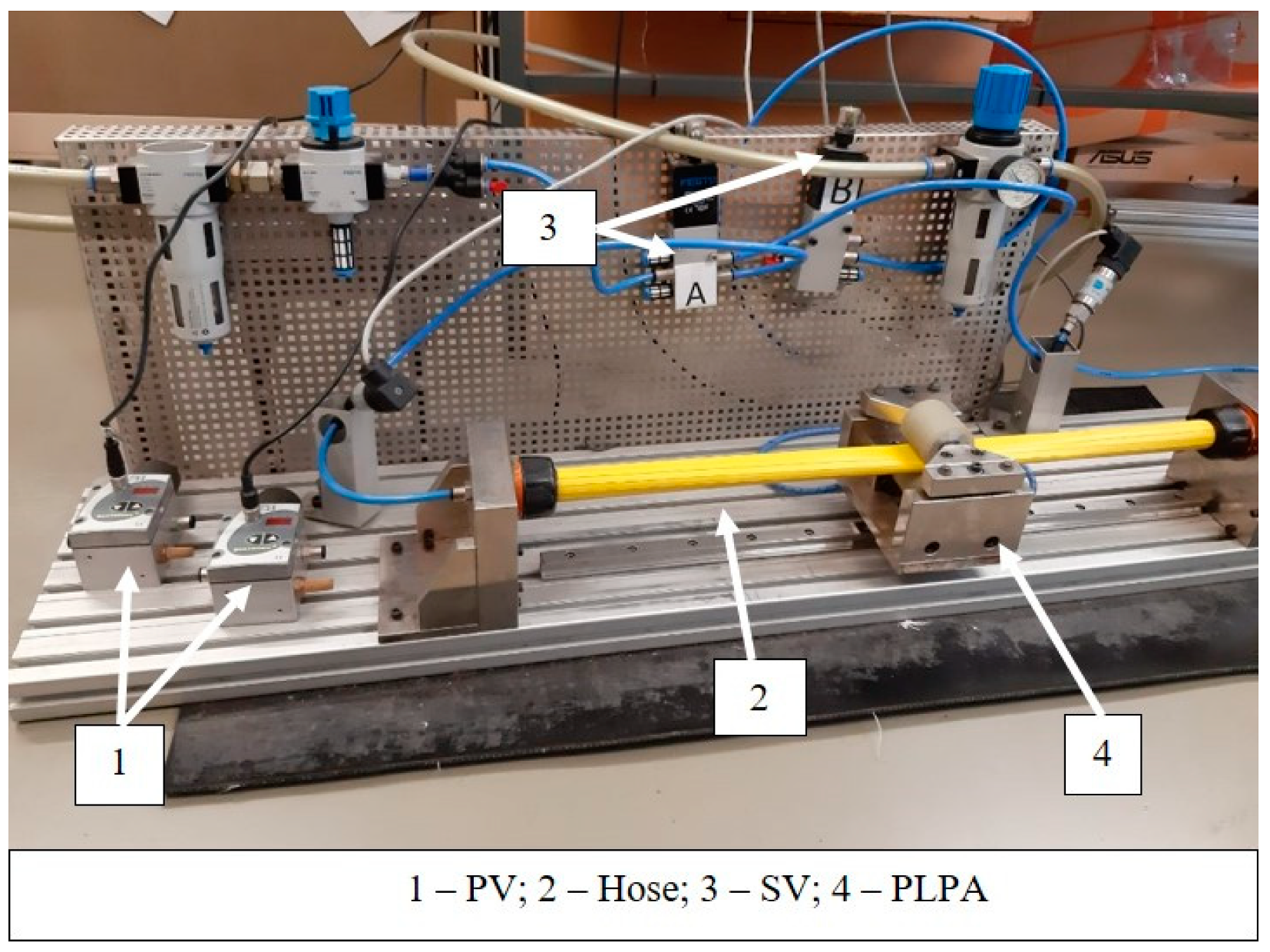
The working principle of the linear peristaltic actuator [12,13,16] can be described as follows: a hose is divided into two chambers by two rollers pressed against it. When compressed air is fed to one end of the hose, a pressure difference is created between chambers that move the rollers. The rollers are connected to a carriage that runs on a mechanical guide absorbing forces and torques that act on the system, as depicted in Figure 1, which shows the experimental setup used in this work.
The experimental setup comprises of not only a PLPA mounted on a carriage, which runs over a monorail guidance system manufactured by Bosch Rexroth AG, Lohr am Main, Germany (IMS series), but also two FESTO servo-valves (SV, reference MPYE-5-1/8-HF-010-B) for flow control and two proportional pressure-reducing valves (PV, reference ASCO SENTRONICD) for pressure control of the compressed air in each chamber. These valves were used for friction and leakages experimental determination, along with a Hastings HFM 201 mass flow meter. Additionally, the setup includes two quick exhaust valves FESTO SEU and conventional electromechanical control components. Additionally, the system comprises of two pressure transducers with a 0–10 bar range and an accuracy of 0.2% of the full-scale value (DRUCK PTX 1400), and a position encoder with a 5 μm resolution, ±0.75 μm interpolation accuracy and ±0.25 μm repeatability. The valves and sensors are connected to a data acquisition and control system. This system is based on a Windows based PC including two data acquisition boards. One board is manufactured by Computer Boards, has 16 bits, with 8 differential analog input channels and two output channels (reference PCI-DAS1602/16). The other a one is an encoder board from Measurement Computing (reference PCI-QUAD04) that is used to acquire the position encoder signal. The software used to control the system was Matlab/Simulink®, which enables automatic generation of the C code, executable in real time, through the Real Time Workshop.
Given the results obtained in [16] regarding the longevity of the PLPA, several modifications to the original PLPA were made in an attempt to increase its endurance. Namely, the two aluminum rollers on the PLPA have a urethane coating to ensure a smoother transition between the rollers’ stiff metallic core and the hose. Furthermore, in this setup the bottom roller is fixed to the carriage, while the top one’s height is adjustable with the help of two screws on each side. By using a set of four spring washers on each of these screws, the force between the rollers can be imposed. This configuration is named the F configuration, while the configuration where the spring washers are not used, so that the distance between rollers is imposed, is named the Z configuration. A schematic of the carriage with the spring washers is shown in Figure 2. The hoses chosen for this study, similarly to what was done in [16], were the following: (i) Fire TYANA SL (FTS), manufactured by Dexyflex and a working pressure of 5 bar and burst pressure of 14 bar; (ii) HIFLAT LD (HFL), manufactured by FITT and with a working pressure of 6 bar and burst pressure of 18 bar and (iii) FLEXIGOM AIR (FGA), manufactured by Productos Mesa with a working pressure of 30 bar and a burst pressure higher than 90 bar. Details on the hose composition and mechanical proprieties can be found in [16].
2.2. System Model
The system’s model was detailed in [16,21] and is summarized in Equations (1)–(5):
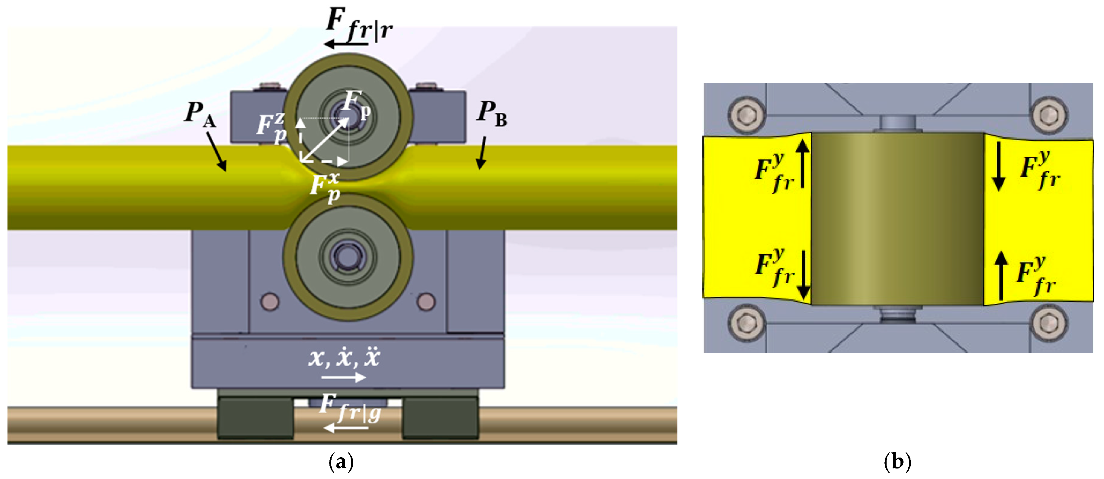
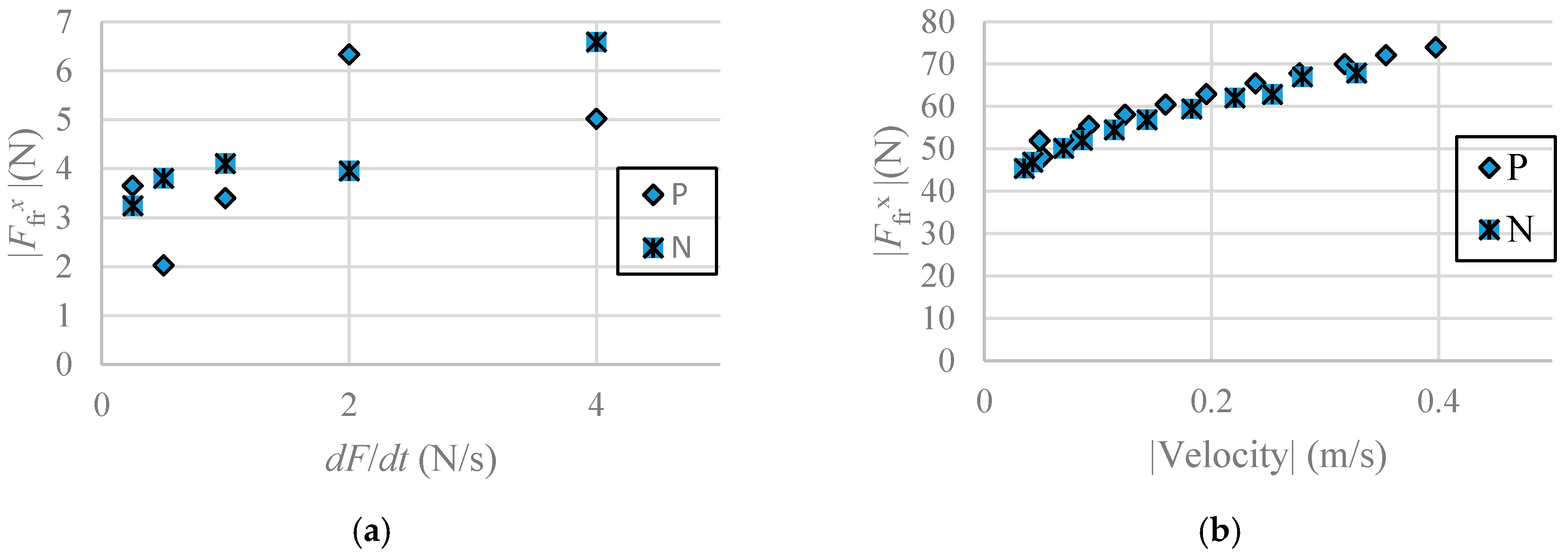
where is the moving mass, , and the position, velocity and acceleration, respectively, the pressure inside the actuator chambers A and B, respectively and is the cross section area of the hose. The total friction force acting on the x direction of the system, , (see Figure 3) can be written as:
where the friction due to the ball bearings of the rollers is represented as , the friction between the monorail guide and the carriage by , the sliding friction in the transversal direction by and is a factor relating the hose flattening velocity in the transversal direction () to the moving mass velocity in the horizontal direction (). The experimental values of , obtained for negative (N) and positive direction motions (P), were determined in [21] and are summarized in Figure 4, for 3 bar backpressure, the source pressure used in the endurance tests presented in the next section.
Under the common assumption that the pressure inside each chamber of the actuator is higher than 0.2 bar, the hose’s cross section can be considered constant [12], so that the volume change inside each chamber is essentially caused by the roller motion.
Assuming also that the temperature variations around the equilibrium temperature are insignificant, the pressure dynamics of chambers A and B can be described as [22]:
In Equation (3), R represents the ideal gas constant for air, represents each chamber’s volume, is the ratio of specific heats for air, the ambient temperature and , the mass flow of air arriving and departing each chamber, respectively. The mass flow of air can be determined performing a balance between (i) the flow retrieved or delivered by the servo valves ([23,24,25]) and (ii) the leakage flow . The leakage between chambers as a function of pressure and spring force was measured in [21]. According to the results obtained in that previous study, was set to be higher than 66% of (1300 N), as this ensures that the leakage is lower than 0.1 slpm at the beginning of the trials, meaning that essentially no leakage occurs.
Under these conditions, the mass flow of air is only dependent on the servovalves model and can be determined as [21]:
where are sonic conductances and is defined by:
with the experimental critical pressure ratio and and are the downstream and upstream pressures of restriction i, respectively.
3. Experimental Tests
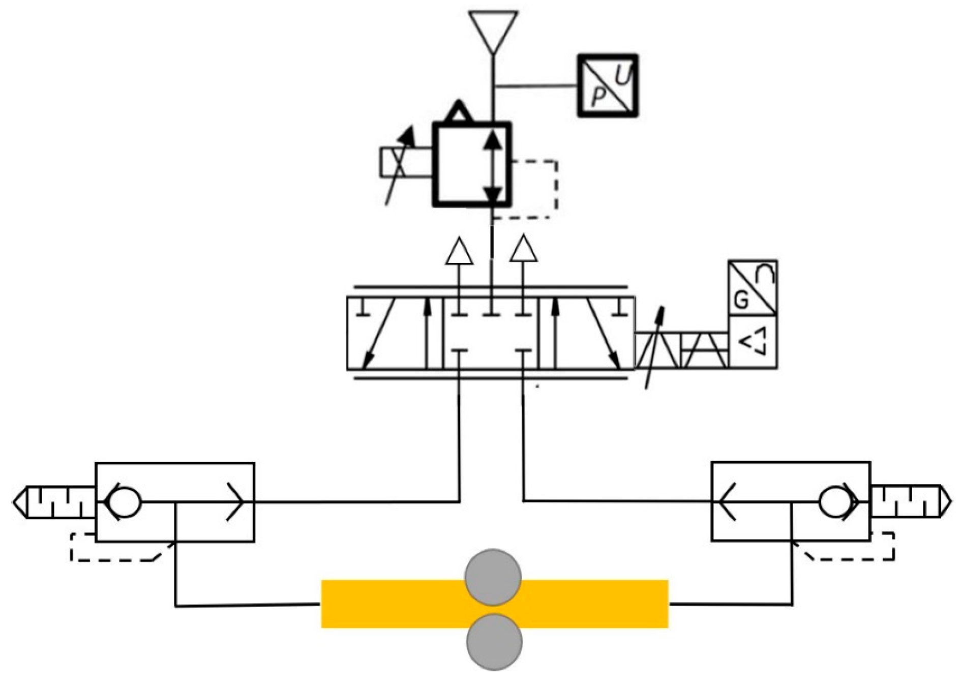
In order to test the hypothesis that the force-imposed configuration might lead to an increased endurance, the PLPA presented in the last section was tested regarding its fatigue behavior. The electro-pneumatic setup used to perform those tests imposes continuous back and forth cycles of the actuator [16] imposed using a Matlab/Simulink implemented program. Figure 5 shows the pneumatic connections used.
The endurance tests were carried out with a stroke of 285 mm, at a source pressure bar, which resulted in a 303 mm/s average actuator speed. The endurance tests were considered finished when the hose presented visible signs of failure, i.e., when it tore or when small holes appeared. When that happened, the system noise changed, alerting the user to stop the test. Five samples of each hose with the force adjustment setup presented in Section 2.1 were tested. Following the same approach used in [16], the hose thickness was measured before and after the endurance tests and the leakages between chambers were measured at the beginning of the trials and at approximately half of the life span. This value was obtained in an initial trial to investigate the number of cycles until failure. Subsequent hoses were tested at half of the number of cycles obtained in that first trial.
3.1. Endurance
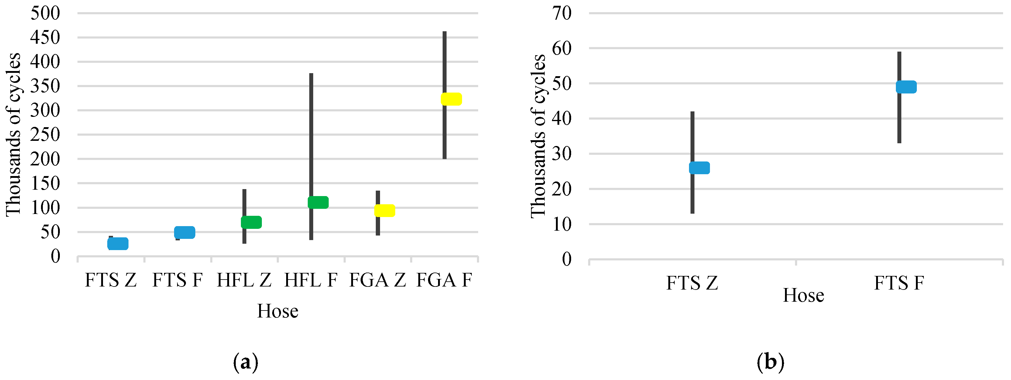
Figure 6 presents the maximum (upper extreme of the vertical lines), average (square) and minimum (lower extreme of the vertical lines) number of cycles obtained until failure using the setup considered in this work (force imposed between rollers, F setup). For comparison purposes, this figure also includes the results of the endurance tests performed in a previous work of the authors [16], using the same type of hoses, but imposing the roller distance (Z).
It is clear from Figure 6 that hoses FGA underwent considerably more cycles than hoses HFL and FTS, in this order. This is valid for both (Z) and (F) setups. A noticeable result lies in the fact that the setup used in this work (F) leads to a much longer endurance than the one used in [16] (Z). The average number of cycles obtained with the (F) setup was 344%, 159% and 188% of the one obtained for the (Z) setup, for hoses FGA, HFL and FTS, respectively. Imposing force instead of distance between rollers, as well as covering the rollers with urethane, proves therefore to have considerable beneficial effects in the PLPA longevity.
3.2. Thickness Reduction
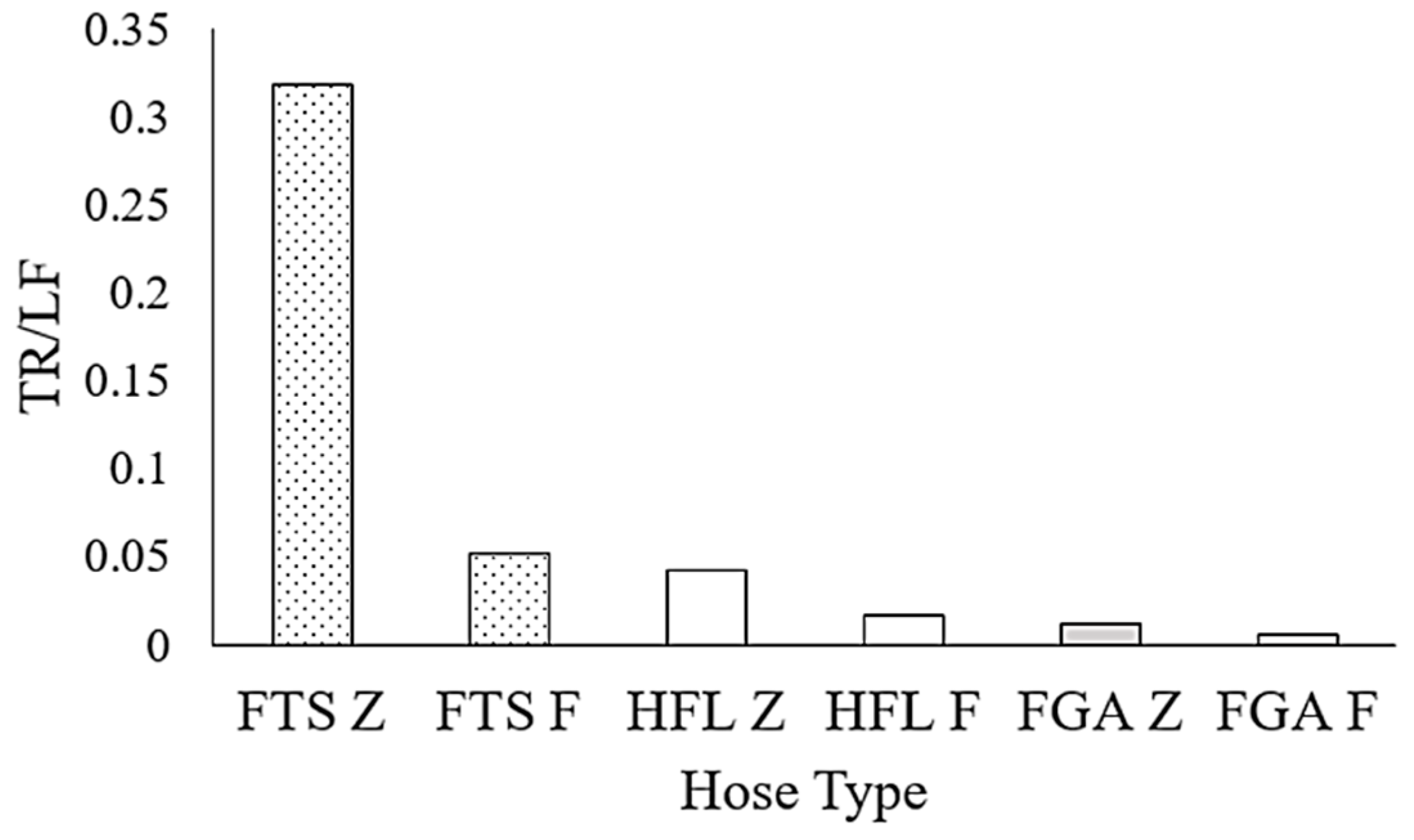
After each endurance test, the thickness of each hose was measured using a digital caliper with a 0.01 mm resolution and following a procedure identical to the one used in [16]. Figure 7 shows the average thickness reduction percentage (TR (%)) that each hose underwent, normalized by the correspondent average life service (LF (thousands of cycles)).
Figure 7 reveals that the F configuration clearly led to a hose thickness reduction per cycle lower than the Z configuration. Additionally, FGA hoses suffered less thickness reduction than the other two types of hoses.
3.3. Leakage During Life Span
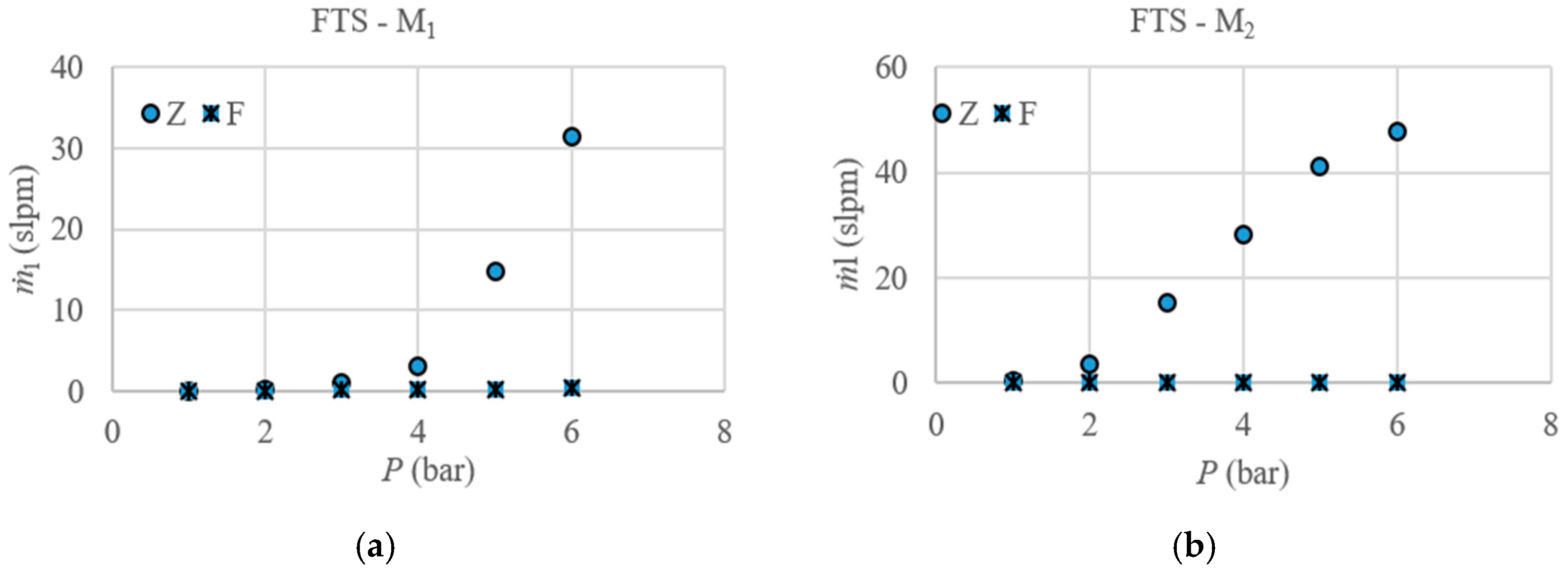
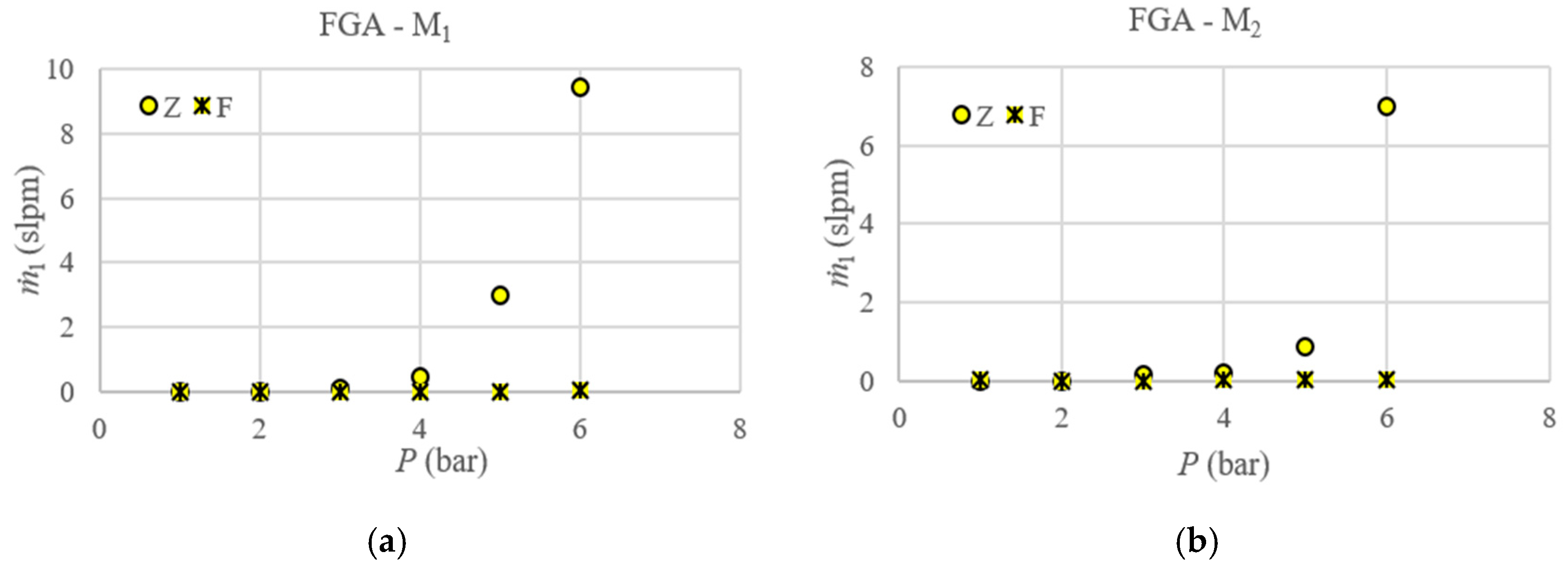
Leakage measurements () at different pressures were performed to one of the tested hoses with force adjustment at the beginning (moment ) and at half of the life span (moment ). Leakages were measured from chamber A to chamber B and vice-versa and then the average of those results was calculated.
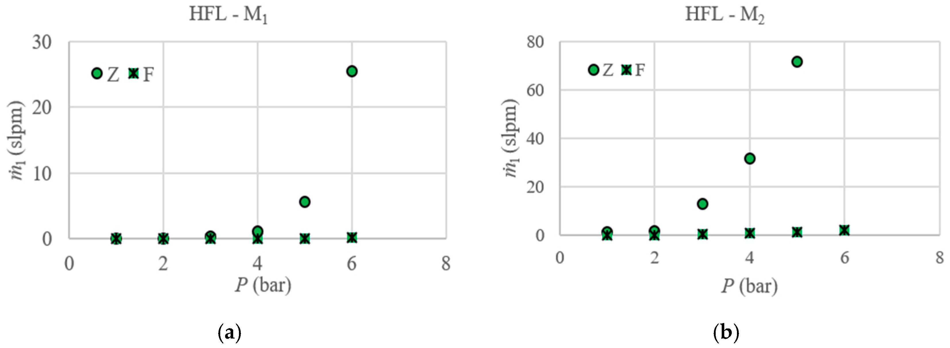
These results were compared to the ones obtained for similar hoses with the setup used in [16], where the distance between rollers was imposed. Figure 8, Figure 9 and Figure 10 present the results obtained for the different hoses considered in this work.
These figures revealed an increase in leakage with input pressure for the case when the distance between rollers was imposed, whereas in the case where force was imposed there was not any significant increase. Imposing the force between rollers had therefore a beneficial effect regarding leakages. This effect can be justified by the fact that the thickness reduction of the hose due to the stress it underwent did not increase the gap between chambers because the springs forced the hose walls to remain together. This is contrary to what happened when the rollers distance was imposed, where this compensation did not occur and therefore the gap between chambers increased as the hose thickness was reduced.
3.4. Hose Failure
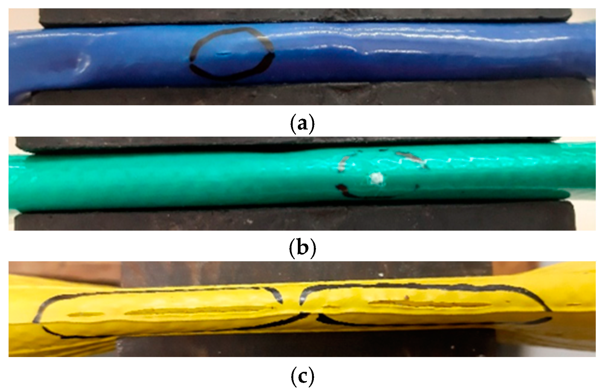
Pictures were taken to each hose after failure. Figure 11 shows an example of the typical failure characteristics found in each hose.
Results presented in Figure 11 are similar to the ones reported in [16]: all hoses failed in the folding region, and while a clear tearing was visible in hoses FTS and FGA, the failure zones in hoses HFL were typically small elliptic shaped holes. It should be underlined that similar results were obtained for the other tested hoses of each type.
4. Investigation on Customized Hose Geometries
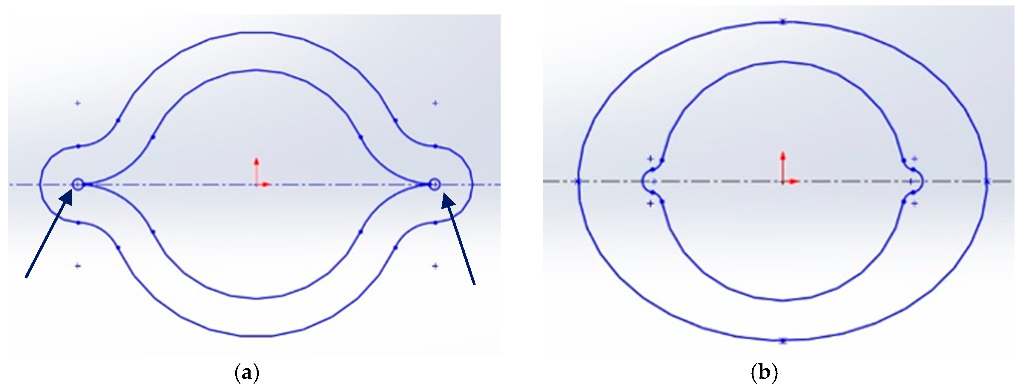
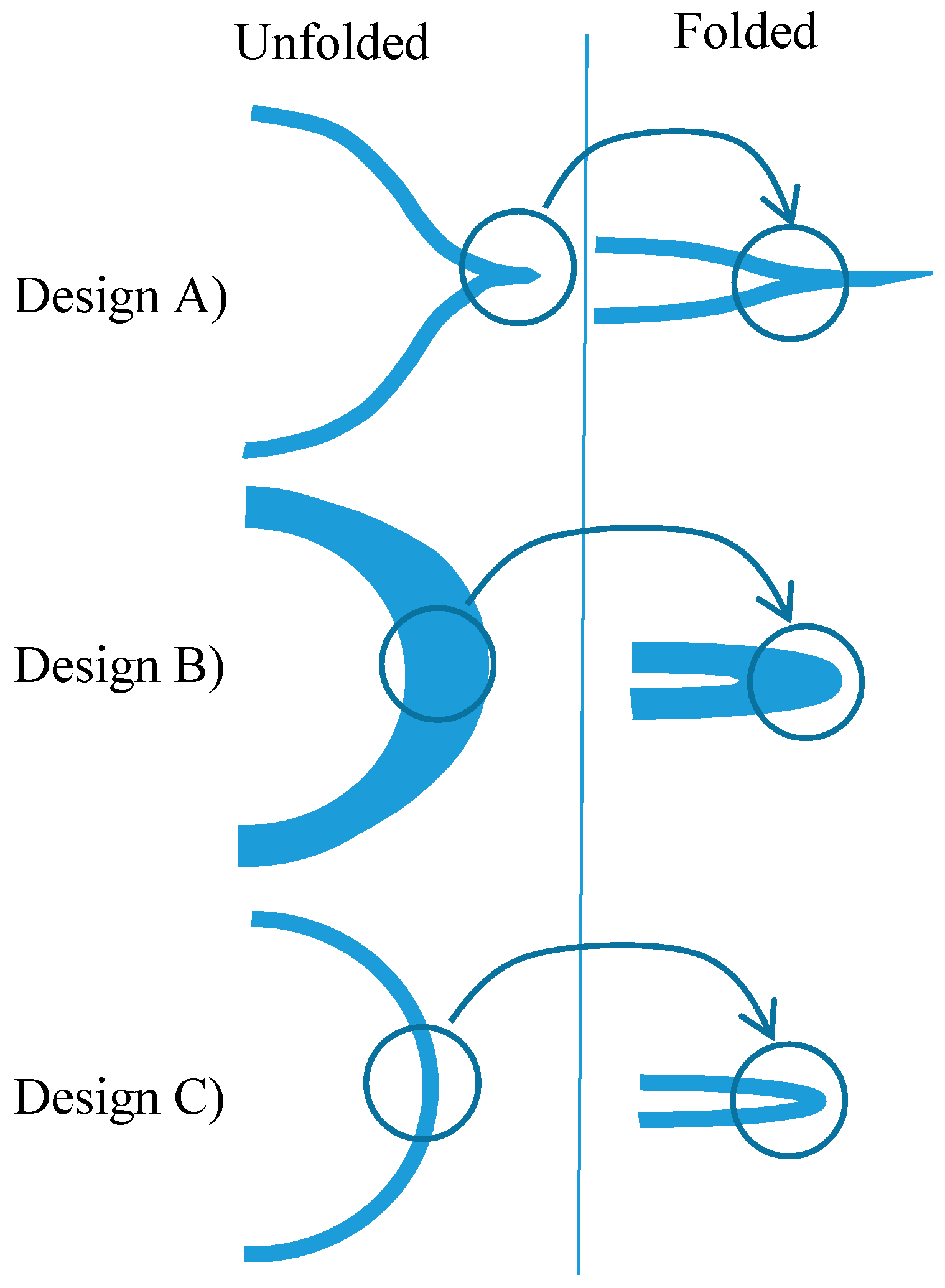
This section was devoted to preliminary findings regarding the use of different hose geometries. Results were then compared with the ones obtained with a circular cross sectional hose. Although results from Section 3 are encouraging as a significant increase in the hose endurance was obtained, possible further improvements were investigated by using different hose geometries. Since, as shown in the previous section, all hoses tore in the folding region, an improvement of the design in that region was pursued. To this end, two different designs were introduced, as presented in Figure 12. Both designs had an inner diameter of 21 mm.
Design A intends to reduce the angle that the walls of the hose have to undergo while being compressed. In fact, in a conventional circular hose, the hose edges are bent when compressed, while in design A the compression does not lead to bending, given its “lip-shape”—please see Figure 13. This is expected to lead to less deformation in the hose edges, thereby contributing to a longer endurance. Design A, however, could lead to an increase of the stress concentration factor due to the inside pressure. For this reason, a circular cross section near the folding region was added, as indicated by the arrows in Figure 12a. It should be noted that the profile thickness of design A is uniform, so that when the hose is folded (fully pressed by the rollers), design A leads to a totally flat hose.
Design B follows a different approach. Instead of reshaping the hose folding region and using the same thickness throughout the profile, design B increases the mass in the folding region—please check Figure 13—so that it gets less prone to fatigue. As a downside, the fact that the thickness is larger at the folding regions could require higher force between rollers to ensure similar leakages.
Design C is the circular design that will serve for comparison purposes. The thickness of the hoses (3.5 mm) was determined based on the fact that commercial silicon rubber hose with a similar thickness was able to withstand more than 300,000 cycles at 1 bar pressure in preliminary experimental tests. These tests were not reported in this paper as they were out of the scope.
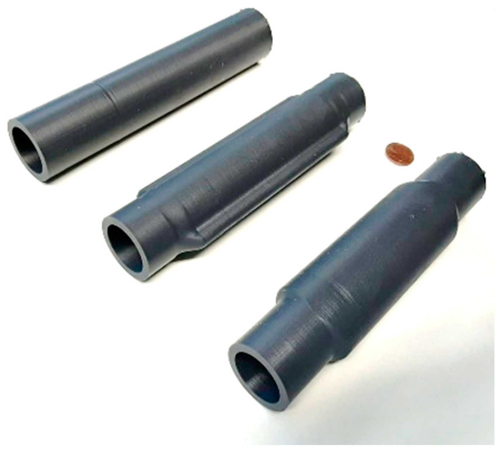
Due to the customized designs A and B, in this work 3D printed hoses were tested, serving as a prototype model for design evaluation and comparison. Figure 14 presents a picture of each prototype.
Three-dimensional printed hoses are not likely to lead to functional prototypes for this application so that their endurance is expected to be relatively low. However, given the final goal of its use in this work—to determine if any of the proposed cross section designs is relatively better than a circular one—3D printing was used as it provides a relatively quick approach to implement the developed designs. In order to fabricate the prototypes, a Stereolitography (SLA) 3D printer (Formlabs 2) and Formlabs flexible resin were used. The main characteristics of the post-cured resin are summarized in Table 1.
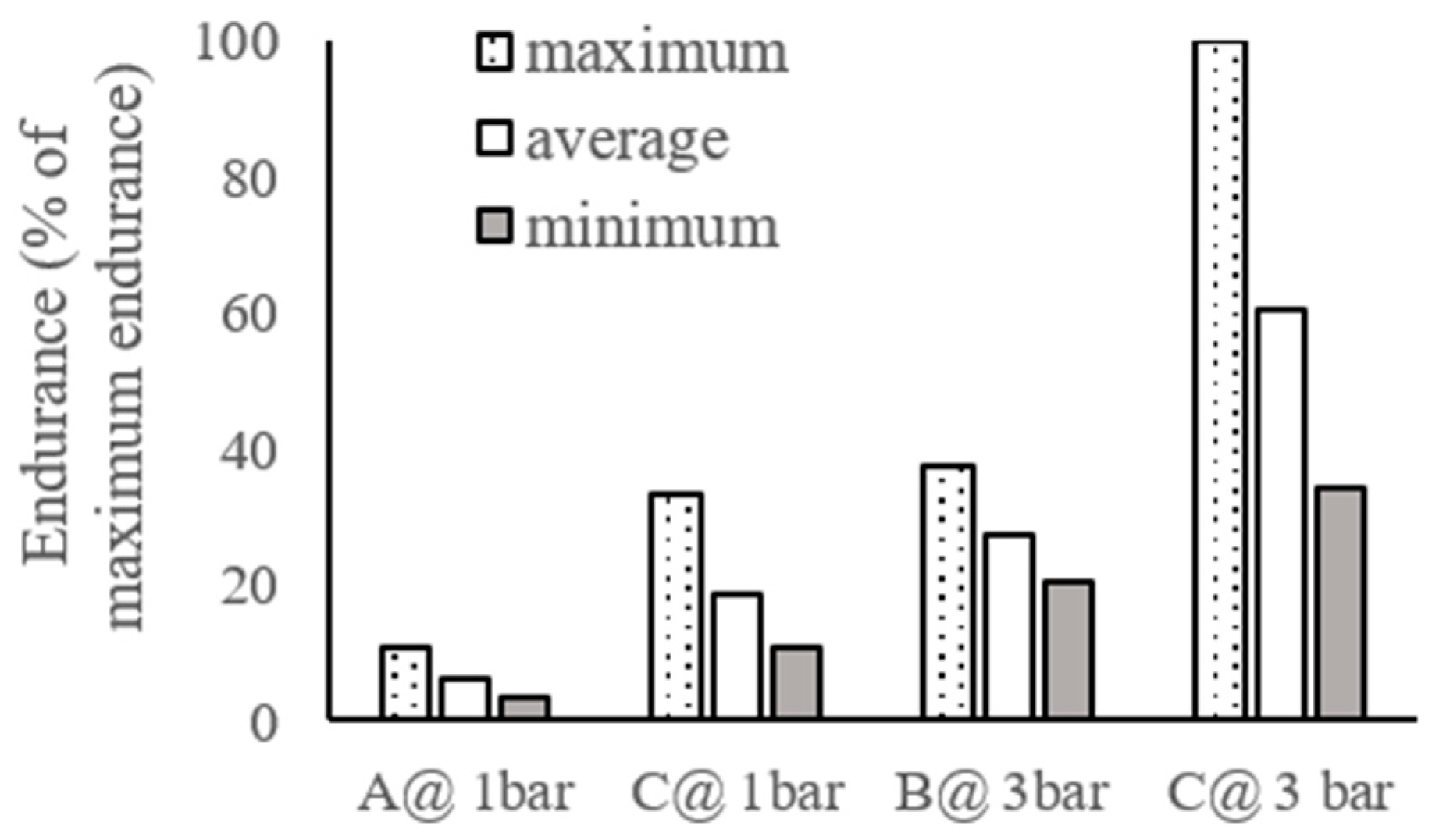
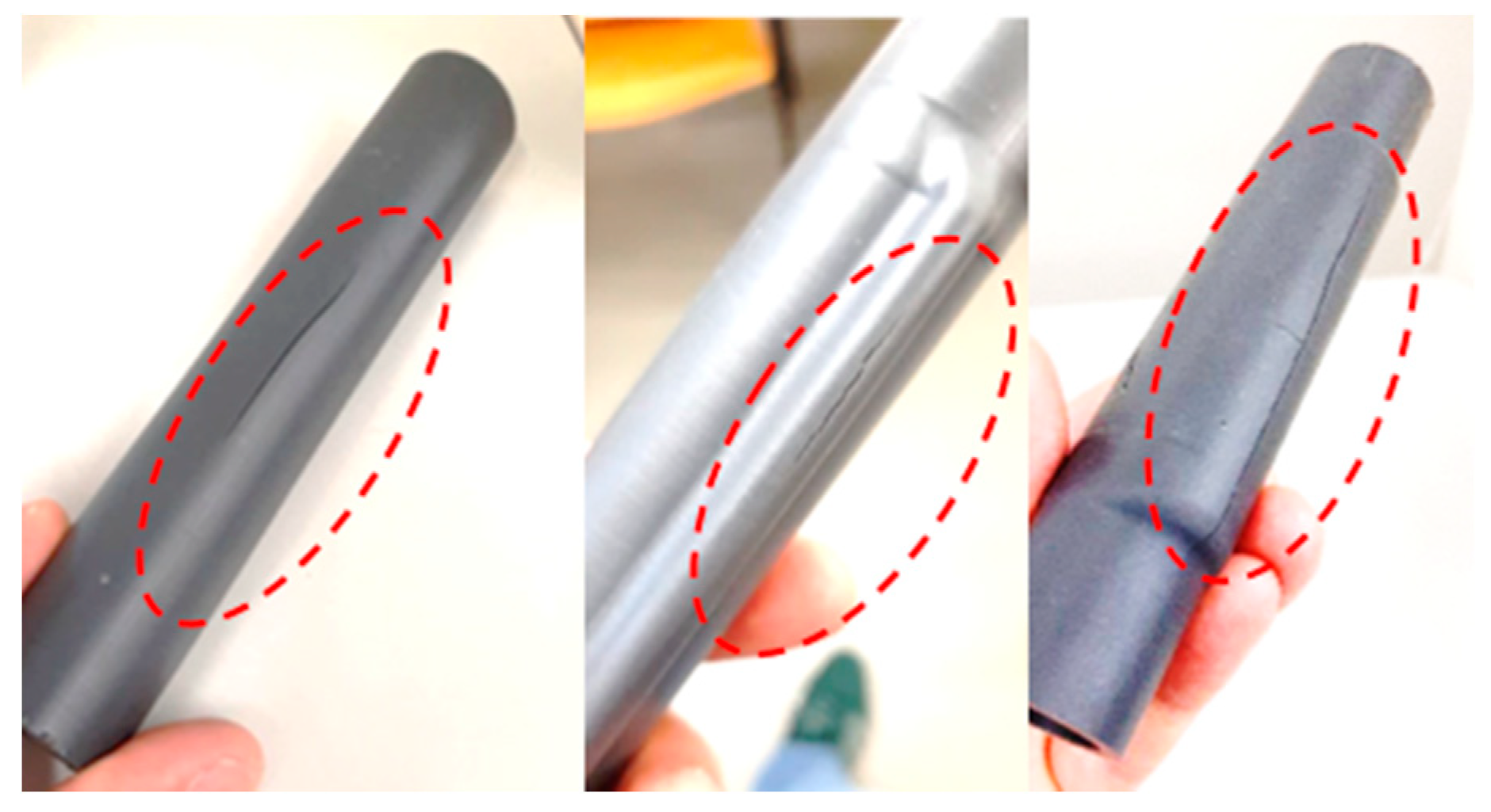
Three-dimensional printed geometries were then post-cured for 180 min at 60 °C in a Formlabs Ultraviolet (UV) cure oven. For each hose design three specimens were tested. Since the endurance of all hoses was relatively short compared to the conventional silicon hose, no leakage or thickness variation measures were made. Additionally, in preliminary trials, it was experimentally found that design A hoses did not withstand the 3 bar pressure. In order to compare each design with a circular one, three design A and design C hoses were tested at 1 bar and three design B and design C hoses were tested at 3 bar. The force between rollers was imposed to ensure that the leakage between chambers was less than 5 slpm in all cases. Achieving lower leakage values was not possible due to the circular cross section near the folding region highlighted in Figure 12a. Figure 15 presents the minimum, average and maximum endurance results, in the percentage of the maximum number of cycles obtained (155). Figure 16 presents the failure regions of each hose considered.
Results presented in Figure 15 were surprising in several aspects. First, it seems that in contrast to the expectations, the use of higher pressure led to a higher hose endurance. Second, none of the proposed designs led to higher endurance when compared to the use of a circular geometry. This might be because the downsides of both designs superimpose its potential improvements. For instance, the short endurance of design A could be due to the internal pressure combined with the geometrical stress concentration that was introduced to improve the behavior when folding.
As for design B, it led to higher endurance than design A even for higher pressures. However, its endurance was still lower than that of design C. Another downside of design B had to do with the force required between rollers for adequate leakage control (as stated before, the rollers force was adjusted to ensure leakages below 5 slpm in all cases).
Table 2 presents the force required for each case. This force was estimated using the spring washers’ stiffness constant and measuring the spring displacement. As can be seen in this table, design B requires approximately twice the force of design C, leading to more friction forces, which reduce the speed of travel. This is a downside of design B that is due to the fact that the mass increase in the folding region requires a higher compression of the hose walls for total flatness. Design A, on the contrary, led to the lower required force. This is an expected result as design A is more easily flattened that the other designs.
5. Conclusions
In this paper the endurance of a linear peristaltic actuator was investigated in an experimental setup that can impose force (instead of distance) between rollers. The nonlinear model of the system was briefly summarized. Endurance tests were carried out for different hose materials and geometries. The results showed that by using urethane coated rollers and an imposed force (F) configuration, a much longer endurance than the one used in [16] (Z) was obtained. The average number of cycles obtained with the (F) setup was 344%, 159% and 188% of the one obtained for the (Z) setup, for hoses FGA, HFL and FTS, respectively.
The thickness reduction per number of cycles in the imposed force configuration was found to be lower than the one obtained in the imposed distance configuration. This might be one of the causes of the increased endurance as it means that the hose was subject to less fatigue per cycle.
The use of the force-imposed configuration was beneficial not only regarding the endurance but also regarding leakages, as it leads to lower leakages when compared to the distance imposed configuration. This study also presented preliminary findings regarding the use of two different hose cross section designs. These designs were thought to enhance the hose endurance in the folding area, the region where the cracks leading to the hoses’ failure appeared. Both designs were however unsuccessful as they led to less endurance than the circular ones. Moreover, the material used to build the prototypes led to very short (maximum of 155) life cycles.
Relation of the hose geometrical design and its mechanical properties will be investigated in future studies using the finite element method. Namely, a thorough analysis will be performed on the folding regions to optimize the design and improve the hose endurance. The impact of the different 3D printable material parameters on the hose stress and strain states will also be analyzed.
Finally, future work will be focused on using the fused layer manufacturing 3D printing method in order to study the hose prototype endurance. Under this context, different elastic materials and printing parameters will be further explored to assess its influence on the hose endurance.
Author Contributions
Conceptualization, J.F.C. and F.G.d.A.; methodology, J.F.C. and F.G.d.A.; software, J.B.P. and J.F.C.; validation, J.F.C., J.B.P. and F.G.d.A.; investigation, J.F.C., J.B.P., F.G.d.A. and M.F.; resources, J.F.C., J.B.P., F.G.d.A. and M.F., writing—original draft preparation, J.F.C.; writing—review and editing, J.F.C., J.B.P. and F.G.d.A. All authors have read and agreed to the published version of the manuscript.
Funding
This research was funded through contract LAETA UIDB/50022/2020 by “Fundação para a Ciência e Tecnologia”.
Conflicts of Interest
The authors declare no conflict of interest. The funders had no role in the design of the study; in the collection, analyses, or interpretation of data; in the writing of the manuscript, or in the decision to publish the results.
References
- Merkelbach, S.; Murrenhoff, I.H.; Fey, I.M.; Eßer, B. Pneumatic or electromechanical drives—A comparison regarding their exergy efficiency. In Proceedings of the 10th International Fluid Power Conference, Dresden, Germany, 19–21 March 2016. [Google Scholar]
- Gauchel, W.; Haag, S. Servopneumatic Clamping System for the Assembly of Battery Cells in the Area of Electromobility. In Proceedings of the 10th International Fluid Power Conference, Dresden, Germany, 19–21 March 2016. [Google Scholar]
- Pinto, J.B. Desenvolvimento de Controlador de Movimento Para Cilindro pneumático de Baixo Atrito. In DEMec; Faculty of Engineering, University of Porto: Porto, Portugal, 2017. [Google Scholar]
- Rus, D.; Tolley, M. Design, fabrication and control of soft robots. Nature 2015, 521, 467–475. [Google Scholar] [CrossRef] [PubMed] [Green Version]
- Belforte, G.; Eula, G.; Ivanov, A.; Sirolli, S. Soft Pneumatic Actuators for Rehabilitation. Actuators 2014, 3, 84–106. [Google Scholar] [CrossRef] [Green Version]
- Feng, N.; Shi, Q.; Wang, H.; Gong, J.; Liu, C.; Lu, Z. A soft robotic hand: Design, analysis, sEMG control, and experiment. Int. J. Adv. Manuf. Technol. 2018, 97, 319–333. [Google Scholar] [CrossRef]
- Kalita, B.; Dwivedy, S.K. Nonlinear dynamics of a parametrically excited pneumatic artificial muscle (PAM) actuator with simultaneous resonance condition. Mech. Mach. Theory 2019, 135, 281–297. [Google Scholar] [CrossRef]
- Sekine, M.; Kokubun, R.; Yu, W. Investigating the Effect of a Mechanism Combined with a Speed-Increasing Gear and a Pneumatic Artificial Muscle. Actuators 2018, 7, 22. [Google Scholar] [CrossRef] [Green Version]
- Robinson, R.M.; Kothera, C.S.; Wereley, N.M. Control of a Heavy-Lift Robotic Manipulator with Pneumatic Artificial Muscles. Actuators 2014, 3, 41–65. [Google Scholar] [CrossRef] [Green Version]
- Hyatt, P.; Kraus, D.; Sherrod, V.; Rupert, L.; Day, N.; Killpack, M.D. Configuration Estimation for Accurate Position Control of Large-Scale Soft Robots. IEEE/ASME Trans. Mechatron. 2019, 24, 88–99. [Google Scholar] [CrossRef]
- Li, S.; Vogt, D.M.; Bartlett, N.W.; Rus, D.; Wood, R.J. Tension Pistons: Amplifying Piston Force Using Fluid-Induced Tension in Flexible Materials. Adv. Funct. Mater. 2019, 29, 1901419. [Google Scholar] [CrossRef]
- Falcão Carneiro, J.; Gomes de Almeida, F. Experimental characteristics of a linear peristaltic actuator. In Proceedings of the 11th International Fluid Power Conference, Aachen, Germany, 19–21 March 2018. [Google Scholar]
- Carneiro, J.F.; de Almeida, F.G. Friction characteristics and servo control of a linear peristaltic actuator. Int. J. Adv. Manuf. Technol. 2018, 96, 2117–2126. [Google Scholar] [CrossRef]
- Poole, A.D.; Booker, J.D. Design methodology and case studies in actuator selection. Mech. Mach. Theory 2011, 46, 647–661. [Google Scholar] [CrossRef]
- Baydere, B.; Talas, S.; Samur, E. A novel highly-extensible 2-DOF pneumatic actuator for soft robotic applications. Sens. Actuators A 2018, 281, 84–94. [Google Scholar] [CrossRef]
- Carneiro, J.F.; de Almeida, F.G.; Pinto, J.B. Endurance tests of a linear peristaltic actuator. Int. J. Adv. Manuf. Technol. 2019, 100, 2103–2114. [Google Scholar] [CrossRef]
- Fateri, M.; Kaouk, A.; Cowley, A.; Siarov, S.; Palou, M.V.; González, F.G.; Marchant, R.; Cristoforetti, S.; Sperl, M. Feasibility study on additive manufacturing of recyclable objects for space applications. Addit. Manuf. 2018, 24, 400–404. [Google Scholar] [CrossRef]
- Gul, J.Z.; Sajid, M.; Rehman, M.M.; Siddiqui, G.U.; Shah, I.; Kim, K.H.; Lee, J.W.; Choi, K.H. 3D printing for soft robotics—A review. Sci. Technol. Adv. Mater. 2018, 19, 243–262. [Google Scholar] [CrossRef] [PubMed] [Green Version]
- Fateri, M.; Gebhardt, A. Selective Laser Melting of Soda-Lime Glass Powder. Int. J. Appl. Ceram. Technol. 2014, 12, 53–61. [Google Scholar] [CrossRef]
- Krause, J.; Bhounsule, P. A 3D Printed Linear Pneumatic Actuator for Position, Force and Impedance Control. Actuators 2018, 7, 24. [Google Scholar] [CrossRef] [Green Version]
- Carneiro, J.F.; Pinto, J.B.; Almeida, F.G.; Fateri, M. Model and Experimental Characteristics of a Pneumatic Linear Peristaltic Actuator. Information 2020, 11, 76. [Google Scholar] [CrossRef] [Green Version]
- Carneiro, J.F.; Almeida, F.G. Reduced order thermodynamic models for servopneumatic actuator chambers. Proc. Inst. Mech. Eng. Part I J. Syst. Control Eng. 2006, 220, 301–314. [Google Scholar]
- Carneiro, J.F.; Almeida, F.G. Pneumatic servo valve models based on artificial neural networks. Proc. Inst. Mech. Eng. Part I J. Syst. Control Eng. 2011, 225, 393–411. [Google Scholar]
- Carneiro, J.F.; Almeida, F.G. A Neural Network Based Nonlinear Model of a Servopneumatic System. ASME J. Dyn. Syst. Meas. Control 2012, 134, 024502. [Google Scholar] [CrossRef]
- Varga, Z.; Honkola, P.-K. Mathematical model of pneumatic proportional valve. J. Appl. Sci. Thermodyn. Fluid Mech. 2012, 1, 1–6. [Google Scholar]
Figure 1.
Experimental setup of the linear peristaltic actuator (unpressurized hose).

Figure 2.
Rollers and carriage (unpressurized hose).

Figure 3.
Mechanical model nomenclature (pressurized hose): (a) front view and (b) top view.

Figure 4.
Friction characteristics: (a) static and (b) viscous.

Figure 5.
Pneumatic connections used in the endurance tests.

Figure 6.
Endurance tests results: (a) number of cycles run until failure and (b) close-up of (a) for the Fire TYANA SL (FTS) hoses.
Figure 6.
Endurance tests results: (a) number of cycles run until failure and (b) close-up of (a) for the Fire TYANA SL (FTS) hoses.

Figure 7.
Thickness reduction results.

Figure 8.
Leakage results for hose FTS: (a) at moment and (b) at moment .

Figure 9.
Leakage results for hose HIFLAT LD (HFL): (a) at moment and (b) at moment .

Figure 10.
Leakage results for hose FLEXIGOM AIR (FGA): (a) at moment and (b) at moment .

Figure 11.
Failure in hoses: (a) FTS; (b) HFL and (c) FGA.

Figure 12.
Cross section designs proposed in this study: (a) design A and (b) design B.

Figure 13.
Effect of rollers compression on the shape of different designs.

Figure 14.
Different 3D printed hose geometries studied in this work. From left to right: Design C, design A and design B.
Figure 14.
Different 3D printed hose geometries studied in this work. From left to right: Design C, design A and design B.

Figure 15.
Endurance of the different designs.

Figure 16.
Failure regions in different designs. From left to right: design C, design A and design B.
Figure 16.
Failure regions in different designs. From left to right: design C, design A and design B.


Table 1.
Main mechanical proprieties of the flexible resin used.
| Ultimate Tensile Strength | Elongation at Failure | Shore Hardness |
|---|---|---|
| 7.7–8.5 MPa | 75–85% | 80–85 A |
Table 2.
Force between rollers required to control leakage for each design.
| A @ 1 Bar | C @ 1 Bar | B @ 3 Bar | C @ 3 Bar |
|---|---|---|---|
| 226 N | 260 N | 799 N | 476 N |
© 2020 by the authors. Licensee MDPI, Basel, Switzerland. This article is an open access article distributed under the terms and conditions of the Creative Commons Attribution (CC BY) license (http://creativecommons.org/licenses/by/4.0/).
Share and Cite
MDPI and ACS Style
Falcão Carneiro, J.; Bravo Pinto, J.; Gomes de Almeida, F.; Fateri, M. Improving Endurance of Pneumatic Linear Peristaltic Actuators. Actuators 2020, 9, 76. https://doi.org/10.3390/act9030076
AMA Style
Falcão Carneiro J, Bravo Pinto J, Gomes de Almeida F, Fateri M. Improving Endurance of Pneumatic Linear Peristaltic Actuators. Actuators. 2020; 9(3):76. https://doi.org/10.3390/act9030076
Chicago/Turabian StyleFalcão Carneiro, João, João Bravo Pinto, Fernando Gomes de Almeida, and Miranda Fateri. 2020. "Improving Endurance of Pneumatic Linear Peristaltic Actuators" Actuators 9, no. 3: 76. https://doi.org/10.3390/act9030076
Note that from the first issue of 2016, this journal uses article numbers instead of page numbers. See further details here.